6
6.0 Drainage System Design
6.1 Drainage systems designed in accordance with BS EN 12056-1: 2000 and BS EN 12056-2:2000 should
be based on the airow data given in Table 2. Typical installaon details in accordance with BS EN 12056-
1: 2000 are given in Figures 3 and 4.
Table 2 A i r o w P e r f o r m a n c e ( l i t r e s p e r s e c )
Nominal size of pipe Airow
32mm 10.1
82mm/110mm 43.0
Note: These results are based on tests carried out by the United Kingdom Building Research Establishment (BRE) in accordance with BS EN 12380: 2002
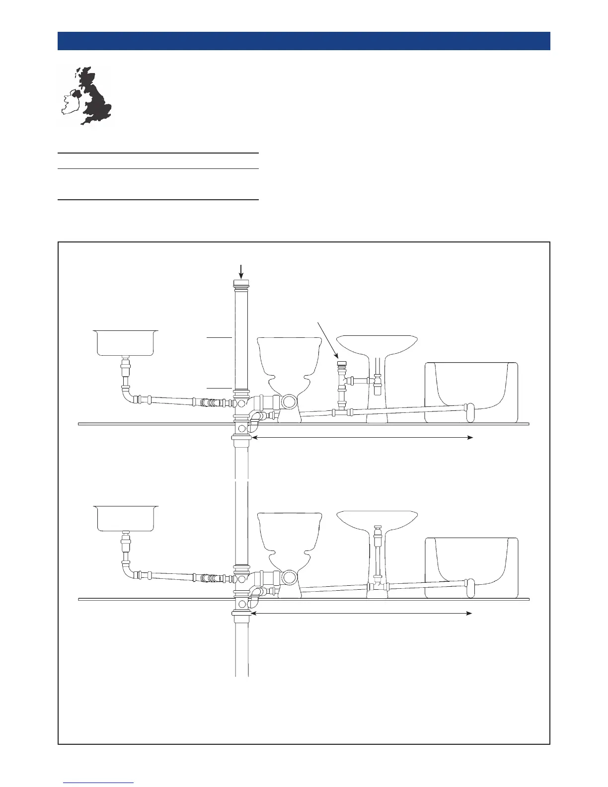
Figure 3 Valves installed in domesc dwellings
(a) venlated by FloPlast
AVE100, AV110, AF110
or AX110
FloPlast AVE100, AV110,
AF110 or AX110
FloPlast
AF32 or AFE32
Minimum
200mm
Greater than 4 metres
(b) unvenlated
Up to 4 metres
NOTES:
• The maximum distance of appliance traps from the discharge stack must be in accordance with BS EN 12056-2: 2000 paragraph 6.4.3 Table 10 and Figure
9 Venlated Branches. The separate venlaon shown on the BS gures may be provided by a FloPlast AF32 or AFE32 Air Admiance Valve which must be
within 1.5 metres of the appliance trap.
• Unvenlated branches BS EN 12056-2: 2000 paragraph 6.4.11, Table 5 and Figure 6.
• Venlaon stacks higher than 45 metres or 10 storeys must not be ed with the FloPlast AVE100/AV110, AF110 or AX110 Air Admiance Valve
 Loading...