8
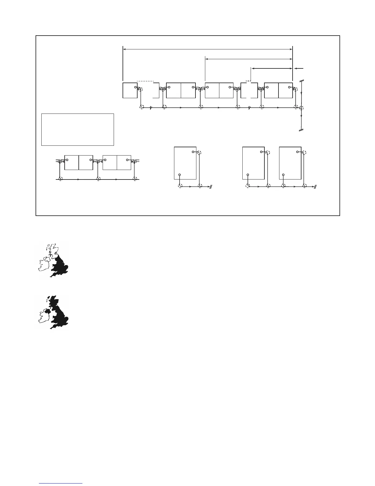
Figure 5 Examples of drain venlaon provisions
6.3 To prevent self-siphonage a connecon to the AF32 or AFE32 valve is required within 1500mm of the trap (see
Figure 4).
6.4 To prevent induced siphonage in a row of wash-basins, a AF32 or AFE32 valve can be ed between
the two wash-basins furthest from the discharge stack (see Figure 4).
6.5 Air admiance valves should not be used as the only venlaon to sepc tanks or cesspools.
6.6 The valve should be installed within the building where it is easily accessible but not subject to inter-
ference from vandals.
6.7 If the valve is to be installed in, or in close proximity to, an habitable space where noise of operaon may cause a
nusiance, then consideraon must be given to the use of a suitable form of sound insulaon.
6.8 In addion, other than those shown in Figure 5, stacks should not be ed with the valves when the connecng
drain(s) are subject to periodic surcharging or are ed with intercepng traps. An open-topped discharge stack or
venlang stack should be used in such cases.
Up to four dwellings fitted with
FloPlast AVE110, AF110 or
AX110 valves
Index
C - Conventional vent stack
G - Gully
F - FloPlast 110mm or 82mm AAV
A - Access
Single multi-storey building with
FloPlast AVE110, AF110 or
AX110 valves
More than one multi-storey building
with FloPlast AVE110, AF110 or
AX110 valves
Row of 20 dwellings with
FloPlast AVE100, AV110, AF110 or AX110 valves
11 to 20 vent at head and mid point
5 to 10 vent to head
up to 4th
non conventional
vent stack
A
A
F
G
F
G
A
A
A
A A
G
C
A
A
C
G
G
F
F
G
F
G
A
A
A
A
20th
13th
12th 11th
10th
9th
8th 3rd 2nd
1st
head of
drain
A
A
F
G
A A
F
F
F
GGG
A
A
C
F
F
A
A
A
C
A
A A
A
F
A
A
F
 Loading...