9
7.0 Eect on water seals
7.1 The valves will admit sucient quanes of air into the stack when they are subjected to a reduced
pressure and there by prevent loss of the water seals in appliance traps.
7.2 Under condions of increased pressure in the drainage system, each valve will remain closed, thereby prevenng
the release of foul air into the building.
7.3 A pressure increase sucient to raise the level in the water seal or to cause foul air to bubble up through the seal is
an indicaon that a drain blockage has occured or that the system is being overloaded or otherwise misused.
8.0 Maintenance
8.1 FloPlast valves do not normally require maintenance.
8.2 In the event of accidental damage or vandalism the valves must be renewed.
9.0 Durability
FloPlast valves are manufactured from materials convenonal in drainage systems. Repeated opening
and closing will not adversely aect the sealing or operaon of the valve. When used in the context of
this data sheet the valves will not be subject to signicant deterioraon and will have a life equivalent to
that of the drainage system in which it is installed.
10.0 Re-use and recyclability
The product contain PVCu, ABS, EPDM rubber and synthec rubber, which can be recycled.
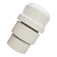
11.0 Installaon
11.1 Installaon must be carried out in accordance with these instrucons.
11.2 FloPlast AF110 & AX110 valves are supplied with a synthec rubber connector enabling a push-t into 100mm and
110mm as indicated in Table 1. Addionally if the rubber connector is removed from the valve a solvent cement socket
will be revealed enabling connecon to 82mm pipes as indicated in Table 1.
11.3 FloPlast AVE100 and AV110 are supplied with solvent cement sockets enabling a solvent cement connecon to
pipes AS INDICATED IN Table 1.
11.4 FloPlast AF32 & AFE32 valves are available in both UK and European designated sizes, supplied with a solvent weld
socket on the main body for 32mm with an adaptor enabling the product to be connected to solvent welded pipe as
indicated in Table 1.
11.5 FloPlast AVE100, AV110, AF110 and AX110 valves must be ed in a vercal posion 200 mm above the highest
branch connecon (see Figure 3). As FloPlast valves are A1 designated to BS EN 12380-1: 2002 it is possible to locate
them below the lowest reservoir being vented.
11.6 FloPlast AF32 and AFE32 valves must be ed in a vercal posion at least 100mm above the pipe being vented.
As FloPlast valves are A1 designated to BS EN 12380-1: 2002 it is possible to locate them below the lowest reservoir
being vented.
11.7 The valves are easily installed in discharge and/or venlaon pipes and eliminate the need to penetrate the roof
covering. Care should be taken to avoid contaminaon of the sealing surfaces, as this may aect airghtness.
 Loading...