Installation 4
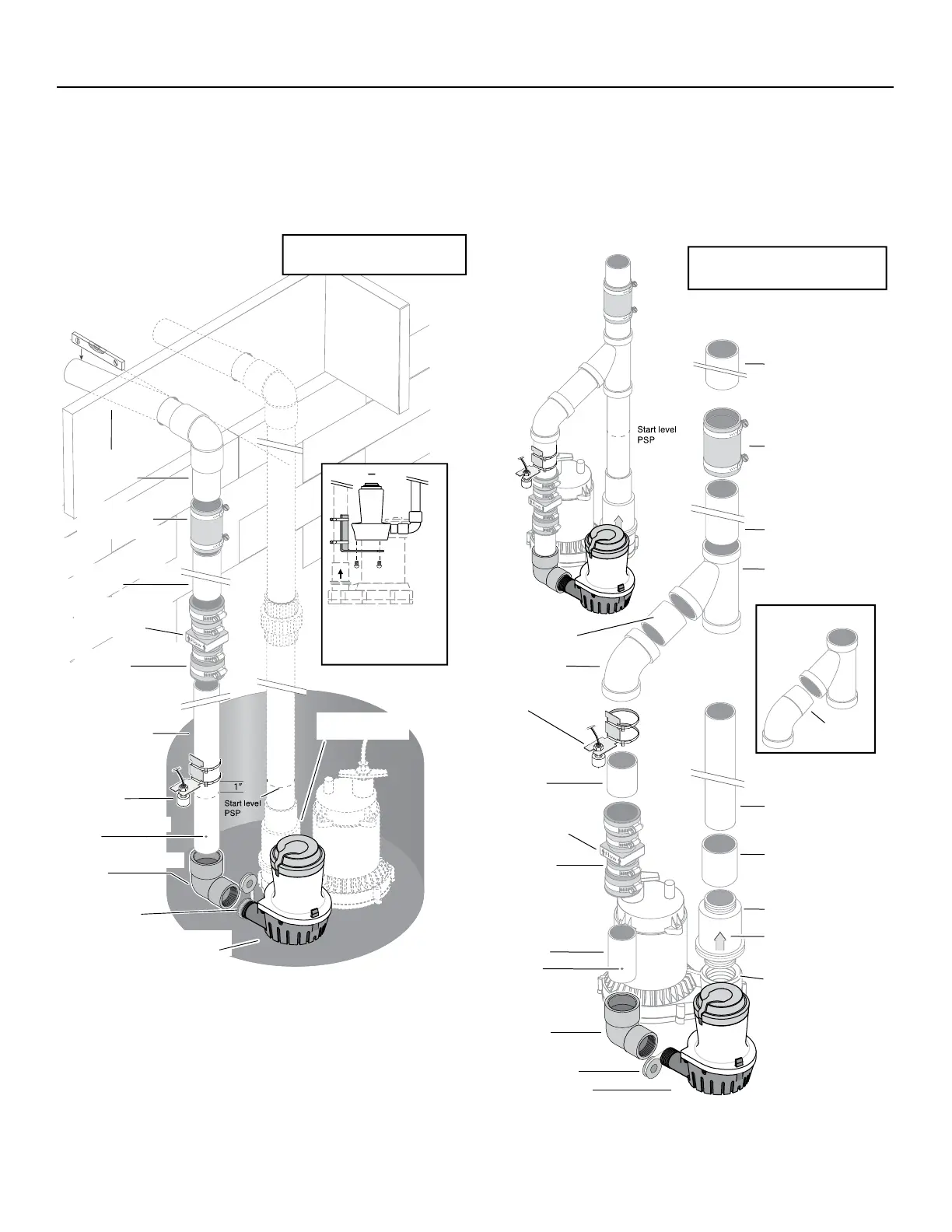
Figure 2: Typical installation with separate
discharge pipes.
Figure 3: Typical installation with common
discharge pipe.
NOTICE:
Check Valve Flapper(s) must swing AWAY and flow arrow(s) must point
AWAY from pump being protected.
The water level when the switch shuts off must be above the BBU
pump intake.
* Supplied with the Battery Backup System.
Items in italics must be purchased separately.
FLOW
Slope DOWN
to outlet
Sill
FP0026-10
Check Valve
(Purchase
Separately)
PTFE pipe thread
sealant tape on all
threaded joints
1-1/2” PVC Riser Pipe
(cut to fit)
1-1/4” FNPTx1-1/2” Slip
Elbow*
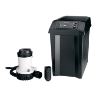
Battery Back Up
Sump Pump*
Lower Discharge Pipe
1-1/2” PVC Pipe
(cut to fit)
Primary Sump Pump
Check Valve
Flow Arrow; Must point
AWAY from Pump
being Protected
1-1/2” PVC Upper
Discharge Pipe
(cut to fit)
Battery Backup
Switch*
If the sump is small,
hang the BBU from
the Primary discharge
pipe on an angle bracket.
Floor
Joist
U74-68 Hose and
Clamp Assembly
(Purchase Separately)
Drill 1/8” Anti-Airlock
Hole
6782 0313a
Not to scale.
Wiring omitted for clarity.
Battery Backup
Switch*
Primary Pump
Discharge Pipe
(cut to fit)
Primary Sump Pump
Discharge Port
Primary Pump
Check Valve
Flow Arrow; Must point
AWAY from Pump
being Protected
45º Slip Elbow
PTFE pipe thread
sealant tape on all
threaded joints
1-1/4” FNPTx1-1/2”
Slip Elbow*
Battery Back Up
Sump Pump*
Thread to Slip
Adapter
45 degree Slip Wye
FLOW
Optional 1-1/2”
PVC Pipe (cut to fit)
1-1/2” PVC Pipe
(cut to fit)
Lower Drischarge Pipe
1-1/2” PVC Pipe
(cut to fit)
AlternateWye/Elbow
Setup
45º Slip Street
Elbow
FLOW
TICE: In this installation, if the Primary Sump Pump (PSP) does not have a
heck valve installed below the wye, you MUST install a check valve for the PSP
wn. This prevents backflow of water into the sump from the Battery Bac
k Valve Flapper(s) must swing AWAY and flow arrow(s) must point
Y from the pump being protected.
he water level when the switch shuts off must be above the BBU pump intake.
*
Supplied with the Battery Backup System.
Items in italics must be purchased separately
ypical installation,
.
alves
must be installed
on the pump side
of the
wye.
FP0026-10
Check Valve
(Purchase
Separately)
1-1/2” PVC Riser Pipe
(cut to fit)
1-1/2” PVC Upper
Discharge Pipe
(cut to fit)
Flow Arrow; Must point
AWAY from Pump
being Protected
U74-68 Hose and
Clamp Assembly
(Purchase Separately)
Drill 1/8”
Anti-Airlock Hole
Not to scale.
Wiring omitted for clarity.