WATER PRESSURE: A minimum of 25 pounds of water pressure is required for regeneration valve to operate effectively.
EXISTlNG PLUMBING: Condition of existing plumbing should be free from Iime and iron buildup. Piping that is built up heavily with
Iime and/or iron should be replaced. If piping is clogged with iron, a separate iron filter unit should be installed ahead of the water
softener.
1. Place the softener tank where you want to install the unit making sure the unit is Ievel and on a firm base.
(Maximum 4 feet apart for twin units.)
3. Solder joints near the drain must be done prior to connecting the Drain Line Flow ControI fitting. Leave at Ieast 6" between
the DLFC andsolder joints when soldering when the pipes are connected on the DLFC. Failure to do this could cause interior
damage to the DLFC.
4. Teflon tape is the onIy sealant to be used on the drain fitting. The drain from twin units may be run through a common
Iine.
8. Place the by-pass in service position.
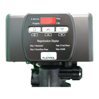
9. Manually index the softener control into “service” position and Iet water flow into the mineral tank. When water flow stops,
close inlet valve, pIace control in “backwash” position to relieve head of air, then gradually open inlet valve to purge remain
ing air in tank. Return control to service position.
10. Electrical: All electrical connections must be connected according to codes. Use electrical conduit if applicable. Plug into
power supply.
5. Make sure that the floor is clean beneath the saIt storage tank and that it is Ievel.
6. Place approximately 1" of water above the grid plate (if used) in your saIt tank. Salt may be placed in the unit at this time.
7. Place in by-pass position. Turn on the main water supply. Open a cold soft water tap nearby and let run a few minutes or until
the system is free from foreign material (usually solder) that may have resulted from the installation.
2. All plumbing should be done in accordance with Iocal plumbing codes. The pipe size for the drain Iine should be the same size as
the drain Iineflowcontrol connection. Water meters are to be installed on soft water outlets. Twin units with (1) one meter shall
be installed on common soft water outlet of units.
BY-PASS VALVES: Always provide for the installation of a by-pass valve.
LOCATION OF SOFTENER AND DRAIN: The softener should be located close to a drain.
CAUTION: Water pressure is not to exceed 120 p.s.i., water temperature is not to exceed 100° F, and the unit cannot be subjected
to freezing conditions.
ELECTRICAL FACILITlES: A continuous 115 volt, 60 Hertz current supply is required. Make certain the current supply is always
hot and cannot be turned off with another switch.
Page 3
Installation Instructions
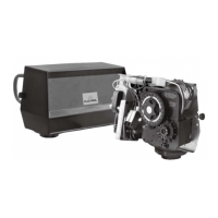
MODEL F40
General Commercial Pre-Installation Check List
 Loading...