Flow-Rite Controls
USA: 616-583-1700 ~ Australia: +61 (0) 73299 3007 ~ www.ow-rite.com
I
S
O
9
0
0
1
:
2
0
0
8
C
E
R
T
I
F
I
E
D
F
L
O
W
-
R
I
T
E
C
O
N
T
R
O
L
S
033111
Using the Timed Delay Switch
To use the med delay switch, place the 3-posion master switch in the “TIMER” mode. The MIN and MAX sengs refer to the
amount of o me between run cycles of approximately 1 minute. MIN will allow the pump to run more oen and MAX will allow
the pump to run less oen. The sengs will allow you to set the intervals from approximately 1 to 12 minutes.
Avoid using the orange or red areas of the Timed Delay switch unless you are in cold water and have a large livewell with just one or
two sh. As you add sh or in warmer water, shorten the me o between cycles by rotang the Timed Delay switch towards the
MIN seng. If water temperatures are above 75º F (24º C), Place the master switch in the constant ON posion.
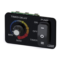
ProTimer Dial
Use the ProTimer med delay feature when
the master switch is set to the “TIMER”
posion. The med delay mode will allow
the pump to run for one minute then o for
1-12 minutes depending on where the dial
is set. MIN and MAX refer to the amount of
me the pump is o between cycles. MIN
will turn the pump o for approximately 1
minute, while MAX will turn the pump o
for approximately 12 minutes.
Master Switch
ON - In this posion the pump will run
constantly, Ideal for water temperatures
above 75º F (24º C) “Timed Delay” feature
is inoperable.
OFF - Use this to keep the pump o when
no water or sh are in livewell.
TIMER - Set the switch in this posion to
acvate and use the “Timed Delay” feature.
MIN
MAX
ON
TIMER
OFF
TIMED DELAY PUMP
1
2
3
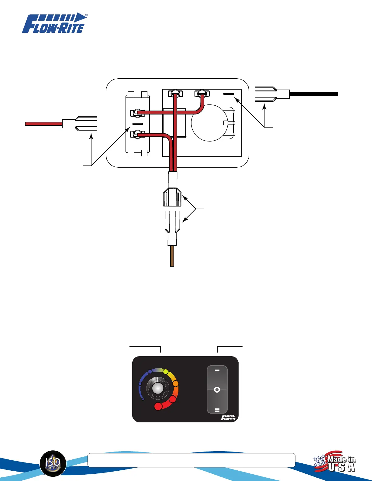
Pump
12v
Grnd
Connect black wire to
ground using supplied
female connector.
Connect 12v power
supply using supplied
female connector.
Connect brown wire with
supplied female connector
to male connector (supplied)
from Pump.
note:
Power supply should be
properly protected with a
5 amp inline fuse or
breaker.
Wiring
All jumper wires and connectors have been included. Follow the diagram below.
 Loading...