Do you have a question about the Flow-Rite ProTimer and is the answer not in the manual?
Use the actual panel as a template to locate and mark the timer switch and master switch mounting holes.
Drill a 3/8" hole for the timer and a larger hole for the ProTimer Plus+ master switch.
Remove the adhesive backing, align, and firmly mount the panel onto the surface.
Install the timer switch from the back and snap in the master switch if applicable.
Turn the knob stem counter-clockwise and place it with the indicator pointing to "MIN".
Attach wires according to the wiring diagram on the next page.
Follow the diagram to connect pump, 12v power, and ground using supplied connectors.
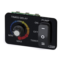
Set the master switch to TIMER mode; MIN/MAX adjust off-time between pump cycles.
Explains the dial settings for timed delay and the functions of the ON, OFF, TIMER master switch.
| Category | Control Unit |
|---|---|
| Amperage | 10A |
| Humidity Range | 0% to 95% non-condensing |
| Relay Output | SPDT |
| Current Draw | 20mA |
| Operating Temperature | -10°C to 50°C |