Fluid-o-Tech Int’l Inc.
161 Atwater St.,
Plantsville CT (USA) 06479
Tel. +1 (860) 276 9270
Fax +1 (860) 620 0193
info@fluid-o-tech.com
Fluid-o-Tech Int’l Inc. Japan
2nd Floor, 4-3-8, Espoir Todoroki,
Todoroki, Setagaya, Tokyo 158-0082
Tel. +81 (0) (3) 6432 1812
Fax +81 (0) (3) 6432 1813
erkkato@fluidotech.jp
Fluid-o-Tech Asia (Shanghai) Co., Ltd.
2/F, Factory building 6 (1), No. 258, Zhijiang Road,
Fengxian District, Shanghai City, Z.P.: 201499 China
Tel. +86 (021) 67100 838
Fax +86 (021) 67100 605
info@fluidotech-asia.com
Fluid-o-Tech srl
Via Leonardo da Vinci, 40
20094 Corsico, Milano, Italy
Tel. +39 02 9995 01
Fax +39 02 9995 0999
info@fluidotech.it
INSTRUCTION
MANUAL
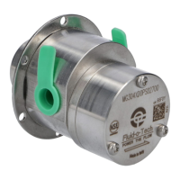
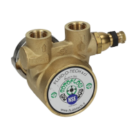
MAGNET DRIVE GEAR PUMPS
MG, MK, MS AND PG SERIES
www.fluidotech.com
The pump should be installed exclusively by authorized
staff. Handle with care.
WARNINGS
• The flange must be handled with care and
should not be grasped with tongs or vices,
since this could cause misalignment of the
magnets and damage of the pump.
• For food applications the pumps (even when
NSF listed) need to be sanitized by circulating
water at 80°C/ 176°F for at least 20 minutes.
• The magnetic coupling does not guarantee a defined value of
the discharge pressure. Should it be necessary to protect the
hydraulic circuit from any possible fluid hammers generated
by the pump, it is vital using a pump, equipped with a bypass
or a safety valve to be installed after the pump itself.
• Dedicated configurations are available if the operating outlet
pressure is in between 10bar/145psi and 15bar/ 217psi. In
case of higher outlet pressure, 15bar/217psi to 20bar/290psi,
please consult the factory.
• The hydraulic circuit should be carefully flushed before starting
the pump.
• The water used for this operation must not be reused, either
during the sterilization or later, but must be discharged.
• In order to avoid any accidental ingress of solid matter which
might damage the internal components of the pump, it is
recommended removing the two protection caps placed on
the inlet and outlet ports of the pump only immediately before
mounting the fittings and the pipework.
• If continuous operation is required, the pump should be mounted
in a well ventilated environment in order to dissipate the heat
produced by the motor.
• To avoid vibrations of mechanical parts and noise, it is advisable
to mount the motor with rubber shock-absorbing supports.
• Particular care must be taken when connecting the pump with
fittings in order to avoid leaks. If Teflon tape is used it is important
not to use too much of it (no more than 2 or 3 turns) to avoid
pieces of PTFE accidentally falling into the pump.
• Before tightening the fittings, hold the part of the pump body
close to the threaded holes. The leverage effects and mis-
manipulation, like the fittings fixation with the pump already
installed onto the motor, can cause components deformation,
leakages, malfunctioning.
• Do not use sealing fluid, as drops may fall into the pipes and
cause the pump block.
• It is advisable to use stainless steel or plastic fittings.
• When substituting just the pump-head, it is necessary to ensure that
the model number of the new pump is identical to the pump to be
changed. Exchanging the pump for a model of different capacity may
damage the system, the motor and the pump itself.
• For pumps equipped with relief valve the thread on the fittings
must not exceed 5 mm. Failure to observe such warning will result
on damage to the relief valve spring.
INSTALLATION
WIRING THE MOTOR TO THE POWER SUPPLY
• The power supply must be consistent with the
electrical data stamped on the motor plate, with
particular regard to voltage, frequency and current.
• The power must be switched off during installation.
MOTOR SELECTION
When the motor is not supplied with the pump it
is necessary to verify that the motor dimensions
and specifications are in line with Fluid-o-Tech
recommendations. Fluid-o-Tech gear pumps need
a motor running at a speed between 800 and 5000
rpm. The flow rate is proportional to the motor speed.
The continuos max torque must be lower than 0.1 Nm
with ferrite-ferrite magnet coupling. Higher torque can
be attained with other types of magnets.
ASSEMBLING THE MAGNET ONTO THE MOTOR SHAFT
Motors with flat shaft (“D” TYPE)
1 Tighten the set screw in its seat in the magnet
holder until it protrudes from the bore of the brass
MG-MK-MS AND PG MANUAL en - 09/21 Ed.
Fluid-o-Tech reserves the right to alter the specifications indicated in this catalogue at any time and without prior notice.
Generally, avoid significant dust or other materials
deposits. The equipment to be installed must be
undamaged and must have been properly stored
before installation, in case of doubt, please consult
Fluid-o-Tech.
In case of overpressure in the system, equip the system
with an adequate safety valve (dimensions, performance,
standards, ...) with the certification of conformity for the
intended ATEX zone.
The bypass valve integrated in certain pump
configurations is NOT to be intended as a safety valve,
but as a simple relief valve for accidental overpressure.
In case the pressure or the temperature (ambient
and/or fluid) exceeded the limit, please consult
Fluid-o-Tech to repair the pump with the replacement of
damaged components and general functioning check.
Inlet and outlet lines should be designed properly for the
required performance conditions and should be executed
accordingly, please refer to the instruction manual. Issues
like cavitation, vapor lock and similar working conditions
must be avoided since they could cause severe problems
and lead to excessive vibrations and premature pump
failure. Lines must be internally cleaned and free of any
foreign particles.
For protection against potentially explosive atmospheres,
it is important that the area around the pump and the
pump itself are clean. During installation and maintenance
use non-sparking tools when working on the pump unit in
a potentially explosive atmosphere.
IGNITION HAZARD ASSESSMENT
IMPLEMENTED BY THE USER
Risks evaluation on the system should be implemented
by the user, according to specific usage and working
conditions, considering:
- analysis of the ignition hazards and their causes;
- frequency and duration of the ignition hazards;
- characteristics of the system, processes and their
interactions;
- entity of consequences.
Through ignition hazard assessment, the user defines
the areas and divides them into zones, with the proper
signals on the access points.
DISCLAIMER
Considerable effort has been made to avoid
inaccuracies and omissions in this manual, if you
should find an error or omission, please contact
Fluid-o-Tech. Fluid-o-Tech reserves the right to update
the design and the specifications of the products at any
time and without prior notice.