415B
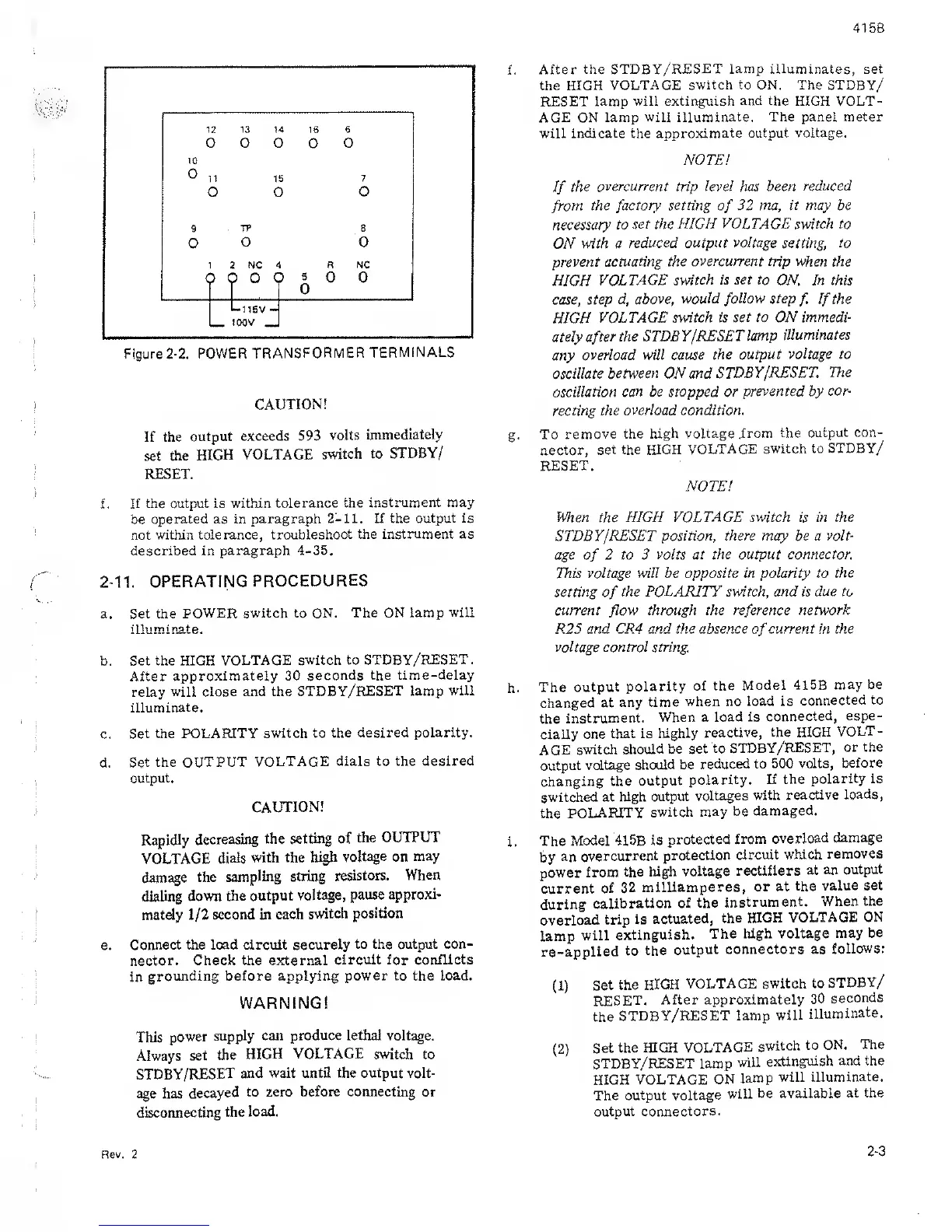
Figure
2-2.
POWER
TRANSFORMER
TERMINALS
CAUTION!
If the
output
exceeds 593
volts
immediately
set
the
HIGH VOLTAGE
switch to
STDBY/
RESET.
f
.
If the output
is
within
tolerance the
instrument may
be
operated as in paragraph
2-11. If the
output is
not within
tolerance, troubleshoot
the instrument as
described in
paragraph 4-35,
2-11.
OPERATING
PROCEDURES
a. Set the
POWER switch to ON.
The ON lamp
will
illuminate.
b. Set the HIGH
VOLTAGE
switch to STDBY/RESET
.
After
approximately 30
seconds the
time-delay
relay
will close and the
STDBY/RESET lamp
will
illuminate.
c.
Set the POLARITY
switch to the
desired polarity.
d.
Set the
OUTPUT VOLTAGE
dials to the
desired
output.
CAUTION!
Rapidly
decreasing
the
setting of
the
OUTPUT
VOLTAGE
dials
with the
high
voltage on may
damage
the
sampling string
resistors.
When
dialing down
the output
voltage,
pause
approxi-
mately
1/2
second in
each
switch
position
e.
Connect the load circuit securely
to the output con-
nector. Check the external
circuit for conflicts
in
grounding before applying
power to
the
load.
WARNING!
This
power
supply can produce lethal voltage.
Always
set
the
HIGH VOLTAGE
switch to
STDBY/RESET
and wait until the output volt-
age
has
decayed
to zero
before connecting
or
disconnecting
the
load.
f.
After
the STDBY/RESET
lamp
illuminates, set
the HIGH
VOLTAGE switch
to
ON. The STDBY/
RESET
lamp will extinguish
and the
HIGH VOLT-
AGE
ON
lamp will
illuminate. The panel meter
will
indicate
the
approximate output voltage.
NOTE!
If
the
overcurrent
trip
level
has
been reduced
from
the factory
setting
of
32
ma, it may be
necessary
to set the HIGH
VOLTAGE
switch to
ON
with a
reduced output
voltage
setting, to
prevent
actuating the
overcurrent
trip when the
HIGH
VOLTAGE
switch is set to
ON. In this
case, step
d, above,
would
follow
step
f.
If
the
HIGH
VOLTAGE
switch is
set
to ON immedi-
ately after
the STDBY
/RESET
lamp
illuminates
any
overload will cause
the output
voltage to
oscillate between ON and
STDBY/RESET
The
oscillation
can be
stopped
or
prevented
by
cor-
recting the
overload condition.
g.
To
remove the high
voltage .from
the output
con-
nector,
set the HIGH
VOLTAGE switch
to STDBY/
RESET.
NOTE!
When
the
HIGH VOLTAGE switch
is
in the
STDBY/RESET position,
there
may be
a volt-
age
of
2
to
3
volts at the output connector.
This
voltage will
be
opposite in polarity to the
setting
of
the POLARITY switch, and is
due to
current
flow
through the reference
network
R25
and CRA and the absence
of
current in the
voltage control string.
h.
The
output
polarity
of the
Model 415B
may be
changed at
any time
when
no
load is
connected to
the
instrument.
When a
load is
connected,
espe-
cially
one
that is
highly
reactive,
the HIGH
VOLT-
AGE switch
should
be set
to
STDBY/RESET,
or the
output
voltage should
be
reduced to
500 volts,
before
changing the
output
polarity. If the
polarity is
switched
at high
output
voltages
with
reactive
loads,
the
POLARITY
switch
may be
damaged.
i.
The
Model 415B
is
protected
from
overload
damage
by
an
overcurrent
protection
circuit which
removes
power from
the high
voltage
rectifiers
at an
output
current
of
32
milliamperes,
or at
the
value set
during
calibration of
the
instrument.
When
the
overload
trip is
actuated,
the HIGH
VOLTAGE ON
lamp
will
extinguish.
The high voltage
may
be
re-applied
to
the
output
connectors as
follows:
(1)
Set
the
HIGH
VOLTAGE
switch
to
STDBY/
RESET.
After approximately
30
seconds
the
STDBY/RESET lamp
will
illuminate.
(2)
Set
the HIGH
VOLTAGE
switch
to ON.
The
STDBY/RESET lamp
will
extinguish and the
HIGH VOLTAGE
ON
lamp
will
illuminate.
The output voltage
will
be available
at the
output connectors.
Rev, 2
2-3
 Loading...