415B
d.
Set the
Model 750A
COARSE and FINE controls to
mid-position.
e.
Set the
Model
4I5B POLARITY switch to the desired
polarity and the OUTPUT
VOLTAGE controls to
same voltage value as the Model
750A INPUT con-
trol.
f.
Set the
Model
845B controls as follows:
POWER
ON
OPR/ZERO OPR
RANGE To reduced sensitivity
(1
volt for example)
g.
Set the
Model
415B
HIGH
VOLTAGE switch
to
ON.
Throw the STANDARD
CELL switch on the Model
750A to MOMENTARY and note the deflection
on
the Model 845AB. Then adjust
the
Model
415B
OUTPUT
CONTROLS, including the vernier, to
achieve zero indication on the Model 845AB. In-
crease sensitivity of the Model 845AB as null is
approached.
h.
Using the COARSE and
FINE controls
on
the Model
750A, adjust
for a final
null on the 10
microvolt
range of the
Model 845AB.
i. Calibrated output
voltages are now available
at
the
Model 750A
OUTPUT VOLTAGE terminals. The
desired voltage value
is selected
with the Model
750A OUTPUT VOLTAGE control.
2-19.
Leakage Current Measurements
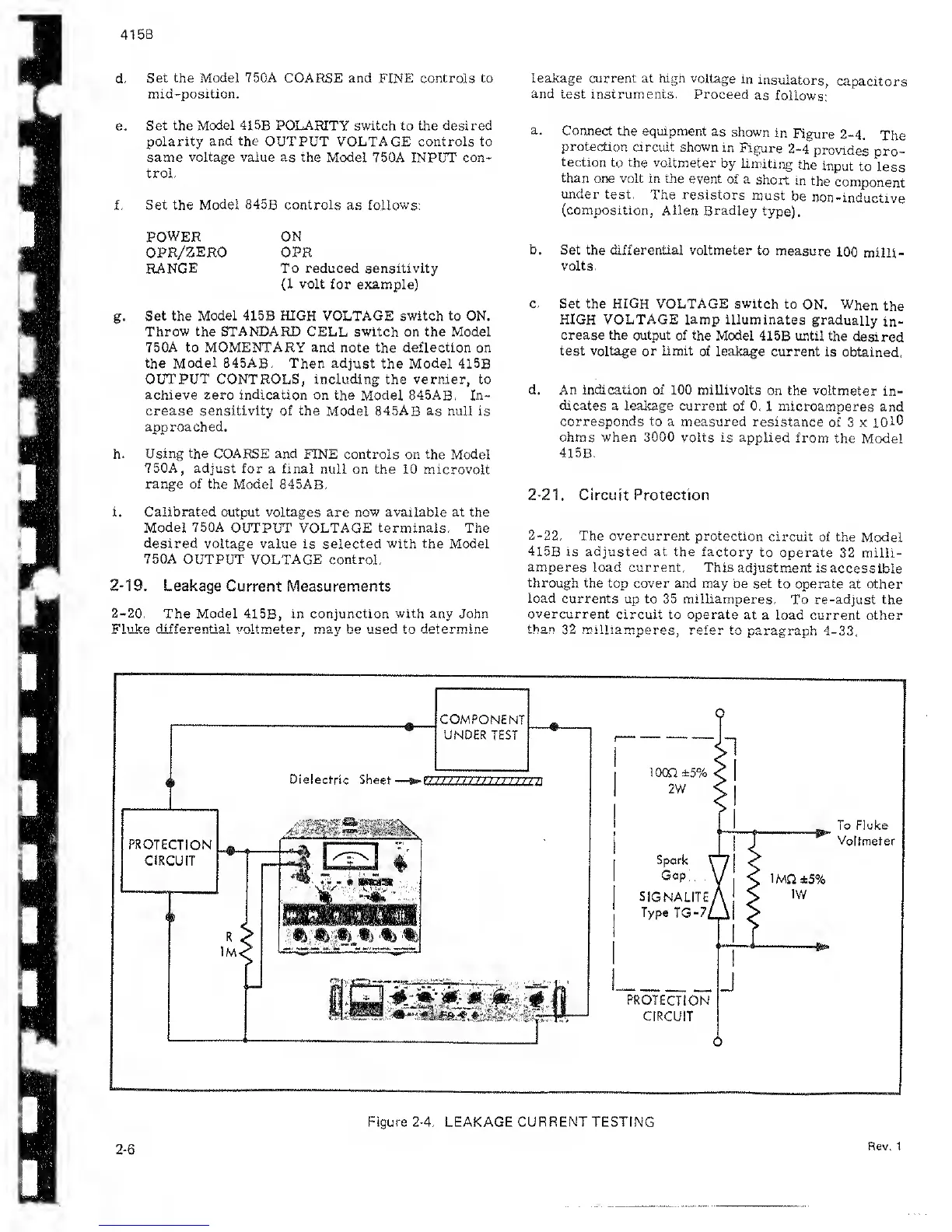
2-20.
The
Model
41
5B,
in conjunction
with any
John
Fluke
differential voltmeter, may
be
used
to
determine
leakage current at high
voltage in
insulators,
capacitors
and
test instruments. Proceed
as
follows:
a.
Connect the equipment
as
shown
in
Figure
2-4.
The
protection
circuit shown
in Figure
2-4
provides
pro-
tection
to
the
voltmeter
by limiting
the
input
to
less
than
one volt in the
event of a
short
in
the
component
under test.
The resistors
must
be
non-inductive
(composition,
Allen Bradley
type).
b.
Set the differential voltmeter
to
measure
100
milli-
volts.
c. Set the HIGH VOLTAGE switch
to
ON. When
the
HIGH VOLTAGE lamp
illuminates gradually
in-
crease the output of the
Model 41
5B
until the
desired
test voltage or limit
of leakage current
is obtained.
d.
An
indication of
100 millivolts
on the voltmeter
in-
dicates
a leakage current of 0.
1 microamperes
and
corresponds to a measured
resistance of
3 x
1010
ohms when 3000 volts is applied
from
the Model
415B.
2-21.
Circuit Protection
2-22.
The overcurrent
protection circuit
of the
Model
415B
is adjusted at
the factory
to operate 32
milli-
amperes
load
current.
This
adjustment is accessible
through
the top cover and may
be set to operate at other
load currents
up to 35 milliamperes.
To re-adjust the
overcurrent
circuit to operate
at a load current other
frhan 39. mill
isi
mnorno fofor
t-rv 4 3 3
2-6
Figure
2-4.
LEAKAGE CURRENT TESTING
Rev. 1
 Loading...