41 5B
REQUIRED
EQUIPMENT
Autotransformer or Variac
DC
Differential Voltmeter
-
Fluke
Model
885A
Voltage Divider
-
Fluke
Model
80F-5
RMS
Voltmeter
-
Fluke Model 93
1A
SPECIFICATIONS
REQUIRED
Output of 0-130
volts
at 3
amperes
or
0-260
volts
at
l.
5
amperes.
Accuracy
of 0.
0025%,
0-1000
volts.
Accuracy
of
0.
01%,
input
voltage to 5000
volts.
Capable of
measuring
non- sinusoidal
voltages
of
less
than
100 microvolts.
Oscilloscope
-
Tektronix Type
541
with
Type D Plug-In
Unit
1 millivolt/centimeter
sensitivity.
VTVM
-
RCA
Voltohrnyst
DC accuracy
±3%
,
DC
Blocking Capacitor
0.
05 uf
minimum capacity,
5000
volts
dc
Power Resistor
16.7
kilohms
±5%,
15 watts.
Composition
Resistors
1,
000 ohms
±5%,
2
watts.
100 ohms
±5%,
2 watts.
1 megohm
±5%,
1
watt.
Silicon Diodes
-
Two required
Type
1N4818 or
equivalent with 50
amperes
surge
capability
and no greater than
20 pf
capacity.
Preamplifier
-
Tektronix Type
123
Gain of 100 with
low level
noise and
hum.
Battery
1. 5 volts.
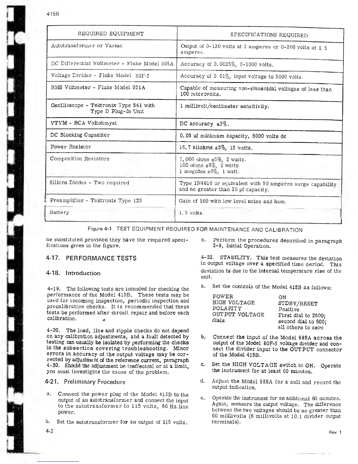
Figure 4-1.
TEST
EQUIPMENT
REQUIRED
FOR
MAINTENANCE AND
CALIBRATION
be substituted
provided they have
the required speci-
fications
given in the figure.
4-17.
PERFORMANCE TESTS
4-18.
introduction
c. Perform the
procedures
described
in paragraph
2-9, Initial
Operation.
4-22.
STABILITY.
This test
measures
the
deviation
in output
voltage
over
a
specified
time
period.
This
deviation is due to the internal temperature
rise
of
the
unit.
4-19.
The following tests are intended for
checking the
performance
of the
Model
415B. These tests may
be
used for
incoming inspection, periodic inspection
and
precalibration
checks.
It is recommended
that these
tests
be
performed after circuit repair and before each
calibration.
*
4-20.
The load,
line
and
ripple checks do not
depend
on any
calibration
adjustments, and a fault
detected
by
testing
can
usually
be isolated
by
performing the checks
in
the
subsection
covering troubleshooting. Minor
errors
in
accuracy
of the
output voltage may be cor-
rected
by
adjustment
of the
reference current,
paragraph
4-30.
Should
the
adjustment
be ineffectual or at a limit,
you must
investigate
the cause
of the problem.
a.
Set the
controls
of the
Model
415B
as
follows:
POWER
HIGH
VOLTAGE
POLARITY
OUTPUT
VOLTAGE
dials
ON
STDBY/RESET
Positive
First
dial
to
2500;
second
dial
to
500;
all
others
to
zero
b. Connect
the input
of the
Model
885A across the
output of the
Model
80F-5
voltage
divider
and con-
nect the divider
input
to
the
OUTPUT
connector
of the Model
41
5B.
c. Set. the
HIGH
VOLTAGE switch
to
ON. Operate
the instrument
for
at least 60
minutes.
4-21.
Preliminary
Procedure
a.
Connect the
power
plug of the
Model
415B to
the
output
of an
autotransformer
and connect
the
input
to
the
autotransformer to
115 volts,
60
Hz
line
power.
b.
Set the
autotransformer
for an output
of 115
volts.
d. Adjust the
Model
88 5A for a
null
and
record
the
output
indication.
e.
Operate
the
instrument for an
additional 60
minutes.
Again,
measure
the output voltage.
The
difference
between
the
two
voltages
should
be no
greater
than
60 millivolts
(6
millivolts at
10:1
divider output
terminals).
4-2
Rev. 1
 Loading...