415B
NOTE!
The unit must have
been
operated
for
one hour
before testing
to
the
following
requirements.
The
cover must be in place during the ripple
test.
NOTE!
Meter readings
will vary with
contact
resistance.
Make comparative readings
with
load
on
Front
and rear
output
terminals.
4-23.
OUTPUT AT ZERO VOLTS. This test checks for
imbalance
in the voltage control circuit.
a. Set the controls of the Model
415B
as follows:
POWER
ON
HIGH
VOLTAGE STDBY/RESET
POLARITY Negative
OUTPUT
VOLTAGE All zeros
dials
b. Connect the Model 885A across the
OUTPUT
con-
nector.
c. Set the HIGH VOLTAGE switch to
ON. The Model
885A at null should indicate
no more than 50
milli-
volts for
both polarities.
4-24.
LINE REGULATION. This test determines
whether the
deviation in output is
within specified limits
for
a change from low to high
line
voltage.
a. Set the
controls
of the Model 41
5B
as
follows:
POWER
ON
HIGH
VOLTAGE
STDBY/RESET
POLARITY
Positive
OUTPUT
VOLTAGE
Second dial to
500;
dials
all others
to zero
b.
Connect the
Mode!
885A
across the front
panel OUT-
PUT connector.
c.
Adjust
the autotransformer
for 103
volts output.
d. Set the
HIGH
VOLTAGE switch
to ON. Adjust the
Model
885A for
a null
indication.
e. Connect
a 16.7K ohm
resistor
across the rear
panel
OUTPUT connector.
The voltage
change indicated
by
the Model
885A shall be
less than
2.0 millivolts.
a.
Set the controls
of the
Model
415B
as follows:
NOTE!
POWER
ON
POLARITY Positive
OUTPUT VOLTAGE Second dial to
500;
dials all others to zero.
b. Adjust the
autotransformer for
103 volts output.
Adjust the Model
885A for
a
null indication.
c. Increase the
line voltage to 127 volts.
The output
voltage
change indicated
by
the Model 885A
shall
be less than
3
millivolts
(6
ppm).
d. Set the HIGH
VOLTAGE switch
to
STDBY/RESET
and disconnect
the Model 885A from
the OUTPUT
connector.
Meter
readings
will vary
with
contact
resistance.
Make
comparative
readings
with
load
on
front
and
back output
terminals.
f.
Disconnect
the
load resistor
and
see
the
POLARITY
switch
to negative.
g.
Repeat
the measurements
of
steps d and
e,
4-26.
RIPPLE.
This test
determines
whether
the-
residual ac
component superimposed
on the dc output
is within specified
limits. Ripple
is
usually higher
with negative
polarity output.
Proceed
as follows:
a. Set
the controls of the Model 41
5B
as follows:
e. Set the autotransformer output
to 103 volts. Set
the first
OUTPUT
VOLTAGE dial
to
2500,
the
second dial to 500 and all others to zero.
f. Connect the
output terminals of the Model
80F-5
voltage
divider to the input of the Model
885A
and
connect the divider input
across the Model
415B
OUTPUT connector.
g.
Set the
HIGH VOLTAGE
switch to ON and adjust
the
Model 885A
for null
indication.
h. Increase the line
voltage
to 127 volts. The voltage
change indicated
by the
Model
885A
should be
no
more than 1. 8 millivolts
(6
ppm) at the 10:1
divider
output.
4-25.
LOAD
REGULATION. This test determines
whether
the output
deviation is within
specified
limits
for a
load
change from
no load to full load. Before
perform-
ing
the
Load Regulation
Test,
verify current,
limit trip
point
is 30
milliamps
or
greater.
If
it is
not, adjust
it according
to
the
procedure
in paragraph
4-33.
POWER
HIGH VOLTAGE
POLARITY
OUTPUT VOLTAGE
dials
ON
STDBY/RESET
Negative
Second
dial to
500;
all others to
zero
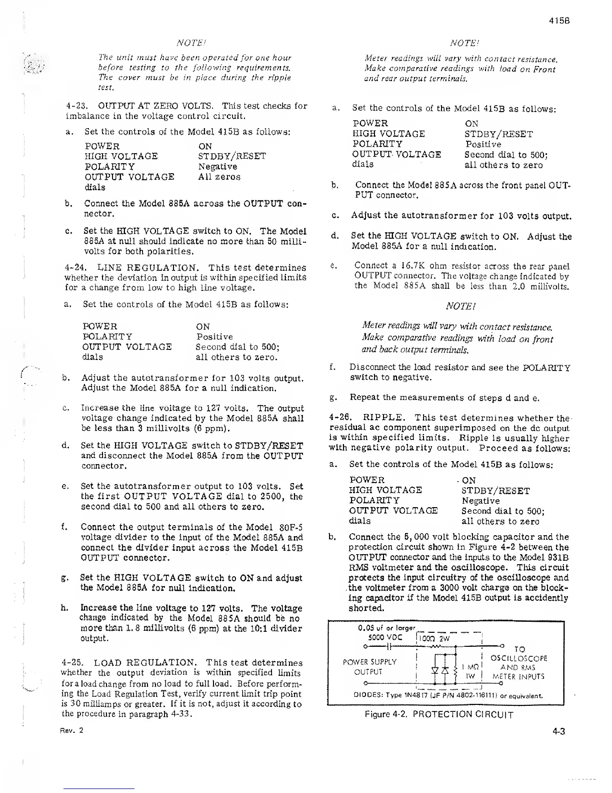
b. Connect the 5,000
volt
blocking capacitor and the
protection
circuit shown
in Figure
4-2
between the
OUTPUT
connector
and the inputs to the Model
93 IB
RMS
voltmeter and the oscilloscope.
This
circuit
protects the
input circuitry of the oscilloscope
and
the
voltmeter from a 3000 volt
charge
on the block-
ing
capacitor if the
Model 415B
output
is accidently
shorted.
0.05
uf or
larger
5000
VDC
ffoCQ
2W
« it
'
0
1 |
w
°
TO
POWER SUPPLY
1
1 I
I
OSCILLOSCOPE
OUTPUT
0
!
tfl
1 MQ
IV/
j
AND
RMS
METER
INPUTS
DIODES:
Type 1N4817
(JF P/N
4802-116111)
or equivalent.
Figure
4-2.
PROTECTION
CIRCUIT
Rev. 2
4-3
 Loading...