41 5B
c.
Set the HIGH VOLTAGE switch to
ON. The ripple
indication shall be less than 1.0
millivolt peak-to-
peak and
less than
100
microvolts
RMS.
d. Adjust the line voltage from 103
to 127 volts and
observe the ripple indication.
Ripple shall be
within the limits specified in
step
c.
e.
Set the first OUTPUT
VOLTAGE dial
to
2500,
the
second dial to 500 and other dials
to zero.
f.
Vary the output
of
the autotransformer between
103
and 127 volts and
observe the ripple indication.
Ripple shall be
within
the limits
specified in step c.
4-27.
OUTPUT VOLTAGE ACCURACY.
To
determine
the accuracy of output
at
each
OUTPUT VOLTAGE
switch setting, perform the procedures
of paragraphs
4-30
and
4-31,
deleting the adjustments.
4-28.
OVERCURRENT CHECK.
To check the trip
point of the overcurrent circuit, perform
the procedures
of paragraph
4-33,
deleting the adjustments.
4-29.
CALIBRATION
4-30.
3000 Volt
Adjustment
4-31.
Before making calibration
adjustments,
the
unit
must have been operated at normal
line voltage
for at
least one hour with an output of
3100 volts. Proceed
as
follows:
a. Set the output of the autotransformer to
115 volts
and set the controls of the Model
415B
as follows:
POWER
POLARITY
HIGH VOLTAGE
Output VOLTAGE
dials
ON
Negative
STDBY/RESET
First dial
to 2500;
second
dial to
500;
others
to zero
b. Connect the output
terminals
of the Model 80F-5
voltage divider across the input terminals of the
Model 88 5A. Connect the divider input across the
Model
415B
OUTPUT
connector.
c. Set the HIGH VOLTAGE
switch to
ON
and adjust
the
Model 885A to
measure
300 volts.
d. Adjust
R26
on the
Amplifier
P/C
Assembly for a
null
Indication
on
the Model 885A. This
adjustment
is
accessible through
the hole in the top
cover.
Make
the adjustment to
better than ±100 millivolts
of 3000 volts
(±10
millivolts on the
Model
885A).
CAUTION!
Use an
insulated
screwdriver
to
adjust R26.
With
negative output polarity,
the
case of this
resistor
is 83
volts above
chassis ground.
With
positive
polarity output, the case would
be
3083 volts
above
chassis ground.
e.
If
the
potentiometer
is
at its
limit
or
the
adjustment
can not be
achieved,
refer to paragraphs
4-46
and
4-48.
f. Set the POLARITY switch to
Positive and
observe
that the
output is
within
the
limits
of step d.
Do
not adjust!
4-32. LINEARITY
CHECK. Proceed
as follows:
a. Set the first OUTPUT
VOLTAGE
dial
to
the 2500
volt
position and all other
dials
to zero.
Connect
the
voltmeter-voltage
divider
combination
across
the OUTPUT
connector.
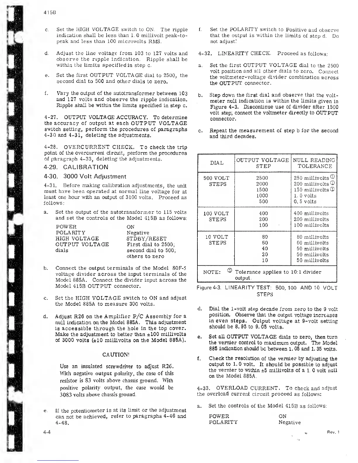
b. Step
down the first dial
and observe that
the
volt-
meter null
indication is
within
the limits
given
in
Figure
4-3. Discontinue use of
divider
after
1500
volt step;
connect the voltmeter directly to
OUTPUT
connector.
c.
Repeat the
measurement of
step b
for the
second
and third
decades.
DL.4.L
OUTPUT VOLTAGE NULL READING
STEP TOLERANCE
500
VOLT 2500 250 millivolts
®
STEPS
2000 200 millivolts
®
1500 150 millivolts®
1000 1 . 0 volts
500
0.
5 volts
100 VOLT
400 400 millivolts
STEPS
200
200
millivolts
100 100
millivolts
1
n
VOLT
80
»n millivolts
STEPS 60
60
millivolts
40 50 millivolts
20 50 millivolts
10 50 millivolts
NOTE:
®
Tolerance applies to 10:1 divider
output.
Figure
4-3. LINEARITY
TEST:
500,100
AND 10
VOLT
STEPS
d.
Dial the 1-volt step decade
from zero
to the 9 volt
position.
Observe that
the output voltage
increases
in even steps. Output
voltage
at 9-volt setting
should be 8. 95 to
9. 05 volts.
e.
Set all OUTPUT
VOLTAGE
dials to zero, then turn
the vernier control to
maximum output. The Model
885
indication
should
be between 1. 05 and
1. 35 volts.
f.
Check
the resolution
of the
vernier by
adjusting the
output to
1.
0 volt.
It should be
possible
to adjust
the
vernier to within
±5
millivolts of a
1. 0
volt
null
on
the
Model
88 5A.
4-33.
OVERLOAD
CURRENT. To
check and
adjust
the
overload current
circuit
proceed
as
follows:
a.
Set
the controls
of the
Model
41
5B
as
follows:
4-4
POWER
POLARITY
ON
Negative
Rev. 1
 Loading...