5 220A
Instruction Manual
3-12
ajs13f.wmf
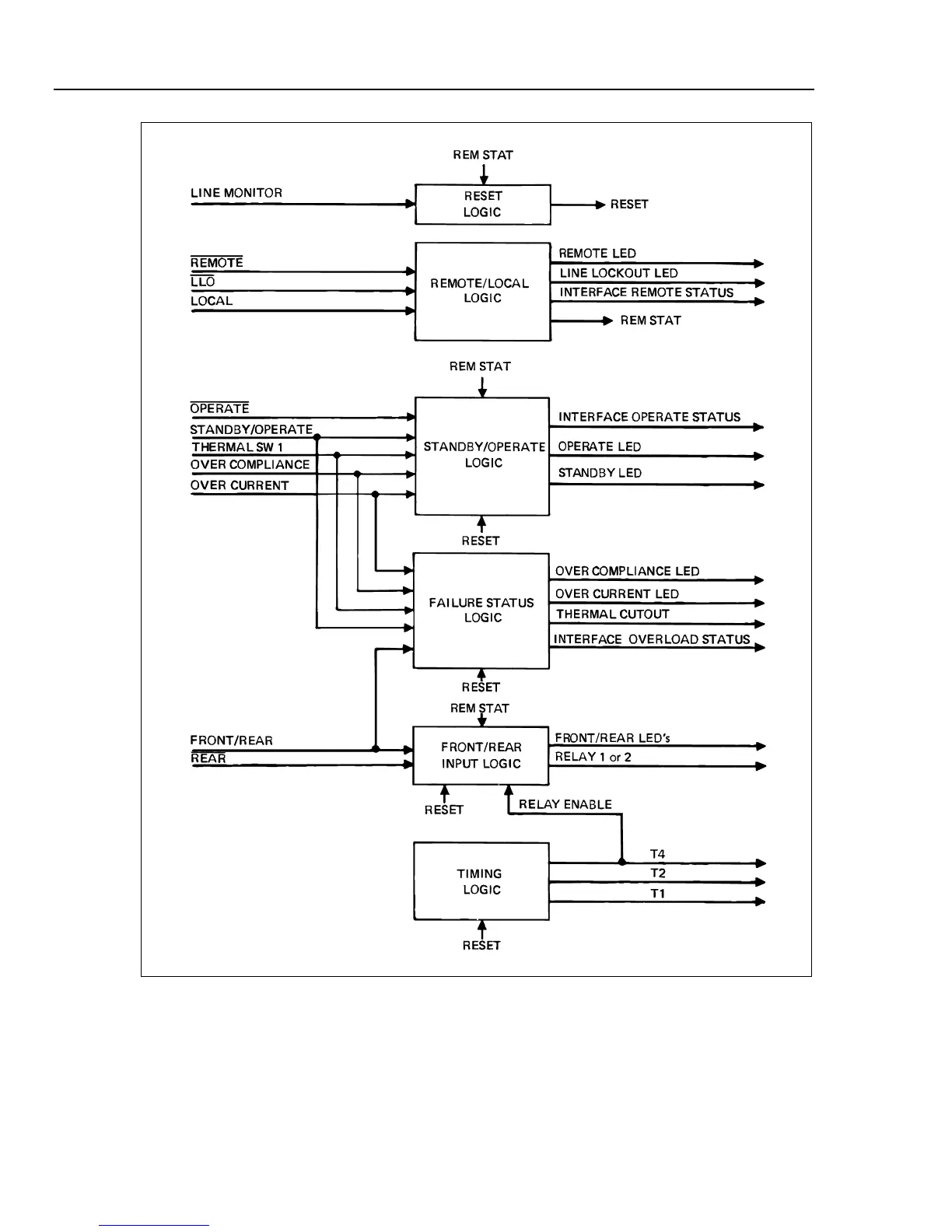
Figure 3-8. A10 Logic Simplified Block Diagram
Loss or interruption of the +15/-15 V dc supply output causes the Line Mon (monitor)
input from the power supply to go low. Normally, the line monitor input is a clipped full-
wave rectified 60 Hz waveform which is generated on the A4 Regulator Assembly. The
negative-going edge is used as the trigger for monostable U11-7 which is timed to
provide an output pulse of approximately 0.1 second. Since the output is longer than the
time between triggers, it will remain active (Q low) as long as the Line Mon (monitor)