5 220A
Instruction Manual
4-26
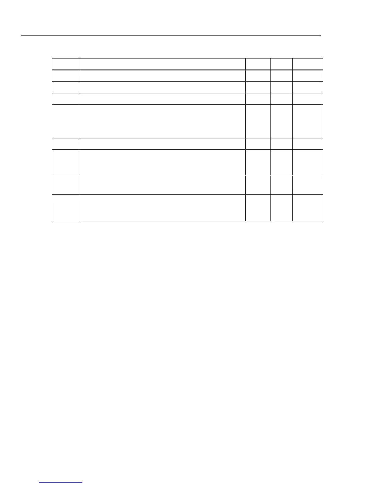
Table 4-7. Analog Section Troubleshooting Guide (cont.)
Step Instruction Yes No Go to
19 Set the 5220A to the operate mode and read the DVM. 20
20 Does the DVM read approximately +0.1 V dc? 26 22
21 Does the DVM read approximately 0 V? 22 23
22 Check relay K1 and associated drive circuits on the A5
Preamplifier PCB Assembly. Also check resistors R1, R2, and
R13 for open circuits. If these are OK, check the Relay 1 drive
signal from the A10 Logic PCB Assembly.
23 Is the DVM reading greater than 0.010 V dc? 24 25
24 The A6 Driver or A7 Output stage is defective. Check voltage
levels on active components to isolate the fault. Repair as
required.
20
25 The A5 preamplifier is defective. Check voltage levels on active
components to isolate the fault. Repair as required.
20
26 The 5220A is operational. Verify instrument compliance with
published specifications by completing the Performance Test
given earlier in this section of the manual.
-