vii
List of Figures
Figure Title Page
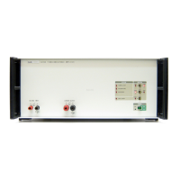
5220A Transconductance Amplifier...................................................................... x
1-1. Outline Drawings................................................................................................... 1-5
2-1. Controls, Indicators, and Connectors..................................................................... 2-3
2-2. Maximum Load Inductance vs Frequency............................................................. 2-8
2-3. Typical Transconductance Error for Inductive Loads ........................................... 2-9
3-1. 5
220A Functional Block Diagram......................................................................... 3-2
3-2. Transconductance Amplifier Simplified Circuit Diagram..................................... 3-3
3-3. Power Supply Functional Block Diagram ............................................................. 3-5
3-4. A5 Preamplifier Functional Block Diagram.......................................................... 3-6
3-5. A6 Driver Functional Block Diagram.................................................................... 3-8
3-6. A7 Output Functional Block Diagram................................................................... 3-9
3-7. A8 Analog Control Simplified Block Diagram ..................................................... 3-10
3-8. A10 Logic Simplified Block Diagram................................................................... 3-12
3-9. Timing Sequence ................................................................................................... 3-14
3-10. A11 MIS Bus Interface.......................................................................................... 3-18
4-1. Internal Component/Assembly Locations.............................................................. 4-3
4-2. Line Voltage Selection........................................................................................... 4-7
4-3. Test Point Location/Identification ......................................................................... 4-19
4-4. Flowchart Summary of Mainframe and Digital Section Troubleshooting Guide.. 4-20
4-5. Flowchart Summary of Analog Section Troubleshooting Guide........................... 4-24
5-1. 5220A Final Assembly .......................................................................................... 5-8
5-2. A1 Motherboard PCB Assembly........................................................................... 5-17
5-3. A2 Power Transformer Assembly ......................................................................... 5-18
5-4. A3 Capacitor Bus PCB Assembly ......................................................................... 5-20
5-5. A4 Regulator PCB Assembly ................................................................................ 5-22
5-6. A5 Preamplifier PCB Assembly............................................................................ 5-25
5-7. A6 Driver PCB Assembly...................................................................................... 5-27
5-8. A7 Output PCB Assembly..................................................................................... 5-29
5-9. A8 Analog Control PCB Assembly....................................................................... 5-32
5-10. A9 Front Panel PCB Assembly.............................................................................. 5-33
5-11. A10 Logic PCB Assembly..................................................................................... 5-35
5-12. A11 MIS Bus PCB Assembly................................................................................ 5-37
5-13. A12 Shunt Assembly ............................................................................................. 5-39
5-14. A13 Output Termination PCB ............................................................................... 5-40
5-15. A14 Extender PCB Assembly................................................................................ 5-41