5 220A
Instruction Manual
5-24
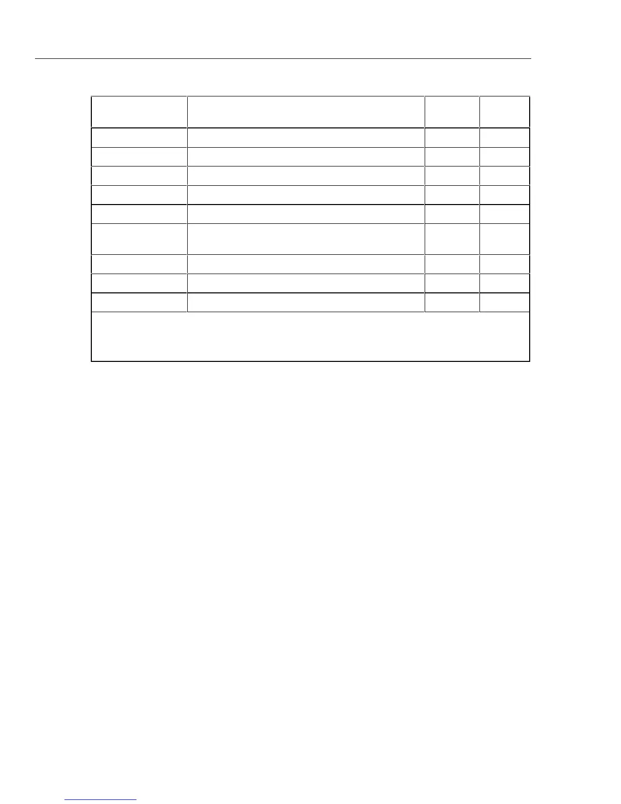
Table 5-6. A5 Preamplifier PCB Assembly (cont.)
Reference
Designator Description
Fluke
Part No.
Total
Quantity
R19 Resistor, MF, 422 Ω, ±1 %, 0.125 W, 100 PPM 288506 1
R21, R23 Resistor, CF, 1 k, ±5 %,, 0.25 W 343426 2
R22 Resistor, CF, 1.2 k, ±5 %, 0.25 W 441378 1
R24 Resistor, CF, 33k, ±5 %, 0.25 W 348888 1
TP1 – TP14 Terminal, Un-insulated, Feed-through, Hole, Turret 179283 14
U1 h IC, Array, 5 Transistors, NPN, 3 Isolated, 2
Differentially Connected
248906 1
U2 h IC, OP AMP, JFET Input, TO-5 429837 1
U3 h Isolator, Opto, LED to Photo Resistor 507475 1
U4 h IC, CMOS, Hex Inverter 404681 1
h Indicates a static-sensitive part.
1. R11 and R12 are factory selected. See Table 4-4.
2. R13 may or may not be installed as factory selected. See Table 4-5.