1.
Connect the Generator to
the controller with an IEEE-488 cable.
2.
Set the address
switch of the Generator as
follows
(as
viewed
from the rear of the
instrument):
00000010
3.
Enter
the following program
into the controller:
1 f
Fluke
1722A BASIC program to
control
a
6062A.
2 ! The
Addrees
of the 6062A is 2.
3
«
2X
10 !
Clear the
6062A so that it is
in
a
known state.
15
INIT PORT 0
20
REMOTE ©A7. \ CLEAR
SAX
iOO
!
SET
THE 6062A.
no PRINT
SAX,
"FR2iOMZ,AP6DB,MRl,Fli5KZ,FIl, AlilSPC, AEl"
999 END
4.
Run the
program
by
typing
on the controller
“RUN (RETURN)
The
6062A Synthesized
RF Signal
Generator can be
connected to
another signal generator in a
master-slave
configuration.
In the
following example, two
generators are configured to
track
each
other in
frequency. This
configuration may
be used to track
frequency, amplitude, AM,
or EM.
1.
Connect two
signal
generators together with
an IEEE-488 cable.
2.
Set the rear
panel address switch
of the first
generator (talker) as follows:
00100000
Cycle the
power of the
first generator so
the software will read
the talk only switch.
3. Set
the rear panel
address switch of
the second generator
(listener) as follows:
01000000
Cycle the
power of the
second
generator
so
the software will read
the listen
only
switch.
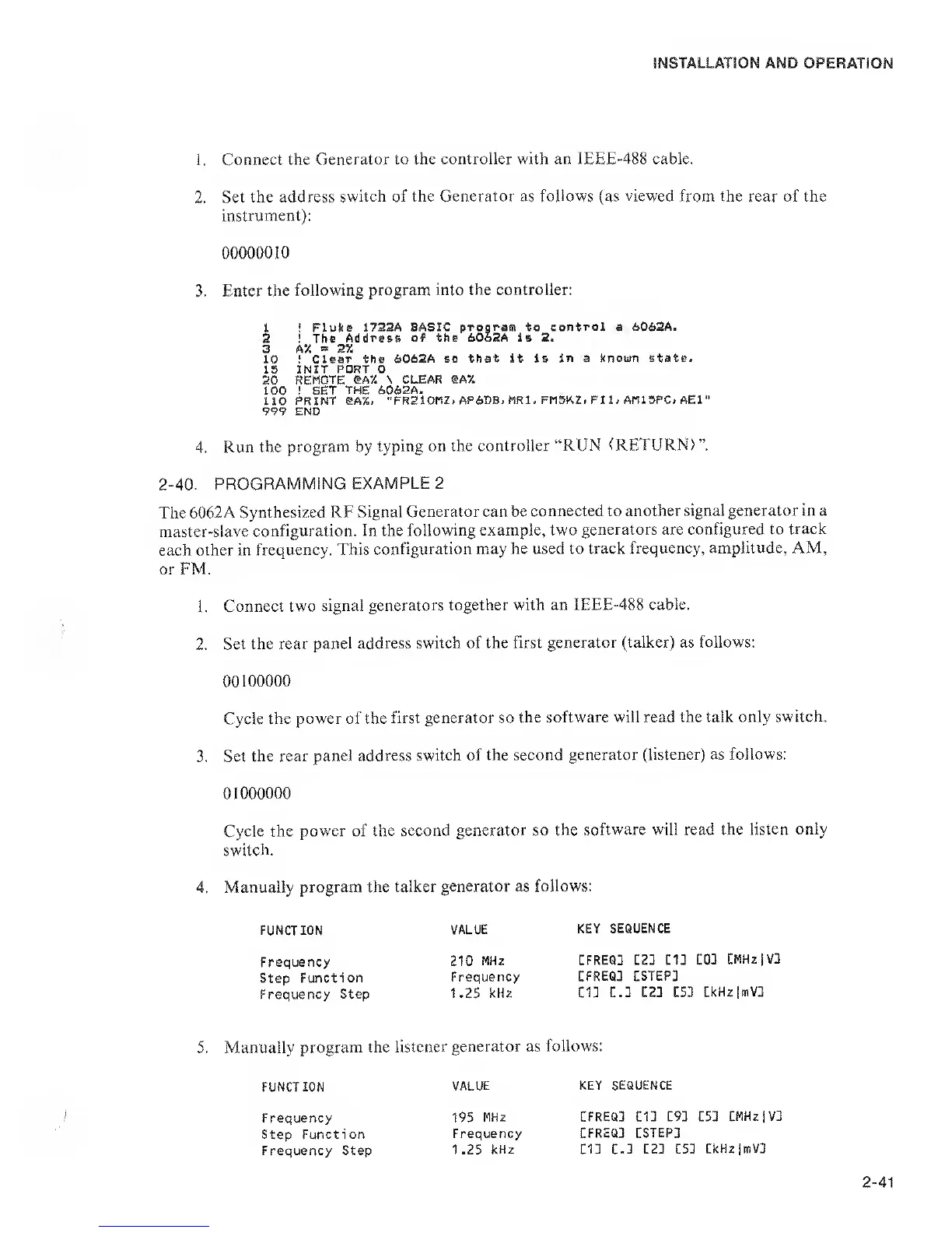
4. Manually
program the
talker generator as
follows:
FUNCTION
VALUE
KEY
SEQUENCE
Frequency
Step
Function
Frequency
Step
210
MHz
CFREQD C2] CID
COD
CMHzjVD
Frequency
CFREQD
CSTEP]
1.25 kHz
Cl] C.] C2] C53
CkHzlmV]
5.
Manually
program the
listener generator as
follows:
FUNCT ION
VALUE KEY SEQUENCE
195
MHz
CFREQ3 CID C9] C5D
CMHzjV]
Frequency
CFREQ3 CSTEP3
1.25
kHz
m E.]
C23 £51
CkHzjmV]
Frequency
Step Function
Frequency Step
 Loading...