NSTALLATION AND
OPERATION
6.
On the
talker generator, press the
[
t
]
STEP
or
[ | ]
STEP keys.
Each lime the
key is
pressed, the frequency of both
generators increases
or decreases
by
i.25
kHz (the
Frequency Step)
at frequencies 15 MHz apart.
Different
functions
on
each generator can be programmed to track in
the
master-slave
configuration. In other words, while the master generator can be programmed to step increase
25 kHz FM, the
slave generator can be programmed to step
25%
AM.
NOTE
To use the
step
feature
for otherfunctions, change the step
function on
the
generators to the desiredfunctions.
2-41.
PROGRAMMING EXAMPLE
3
In the following example, the Generator is programmed by a Fluke 1722A Instrument
Controller
(via the IEEE-488 bus) to the same state as in Programming Example
1.
Additionally, the frequency step size is
set
to 1 .25
kHz,
and the trigger buffer is programmed to
execute
the step
up
command when the trigger command is received. The SRQ mask of the
Generator is set to
generate an SRQ when the RF output
has
settled and the
Generator is ready
for more input from the bus.
The program then enters a loop where it waits for the ready SRQ, sends the GET (group
execute
trigger) interface message to step up the frequency, and waits again.
At
this time,
do
the following;
1 . Connect the Generator to the
controller with
an
IEEE-488
cable.
2. Set the
rear panel addre.ss
switch
of the Generator
as follows:
0000011
1
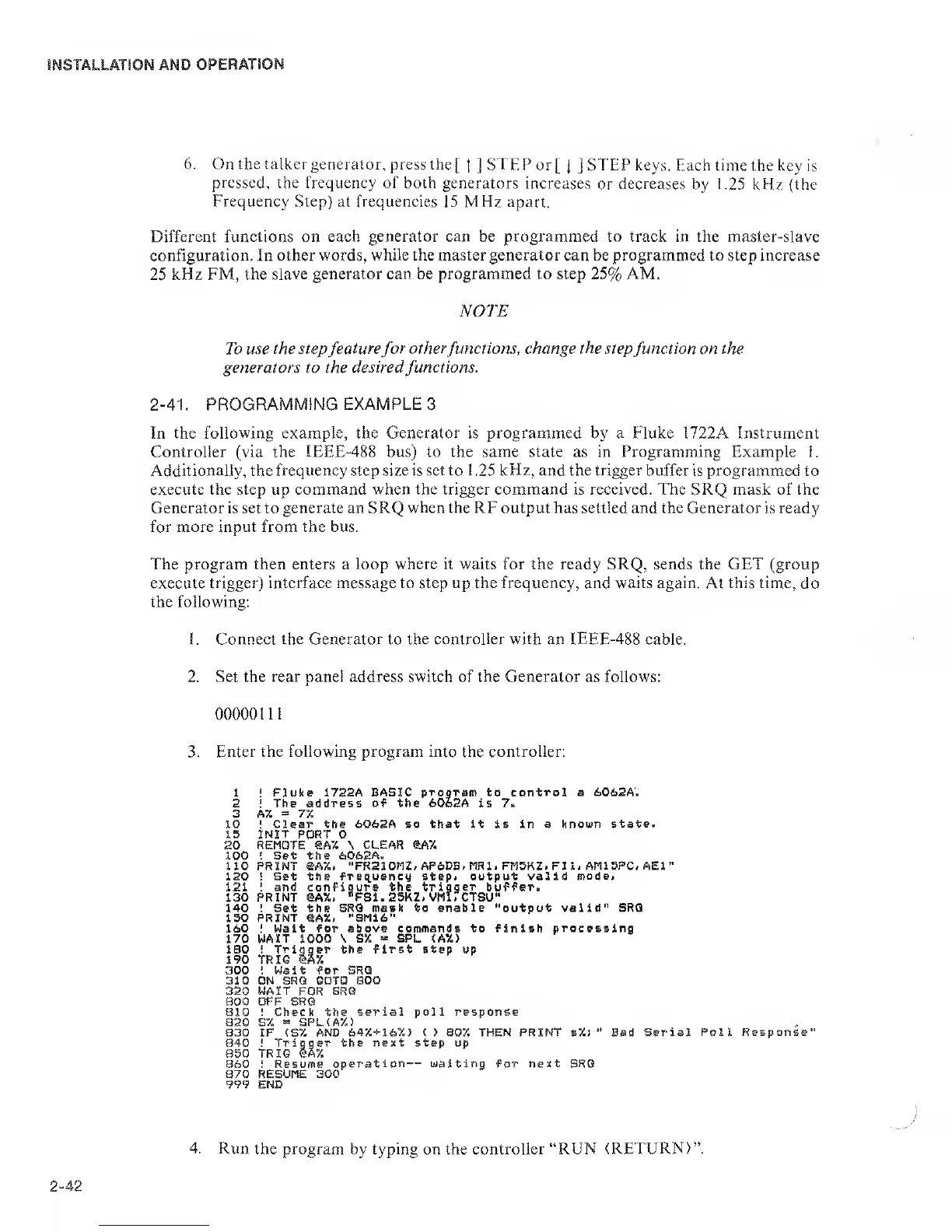
3.
Enter the following program into
the
controller:
20
100
no
120
121
130
140
150
160
170
IBO
190
300
310
320
800
810
820
830
850
860
870
999
!
Fluke 1722A BASIC
program
to
control
a 6062A.
!
The address of the 6062A is 7»
A%
=
77.
!
Clear the 6062A so that it is in a known
state.
INIT
PORT 0
REMOTE SA7. \ CLEAR
®A7.
'
Set
the 606SA.
PRINT @A%,
-FR210I1Z/ AP6DB.MR1, FM5KZ- FIl. AM15PC, AEl”
!
Set the freq^uency step< output valid
mode>
!
and configure the
trigger
buffer.
PRINT ®AX.
*’FS1.25K2. VMirCTSU"
! Set the
SRQ mask to enable "output valid" SRQ
PRINT eA7.. "SM16"
I
Wait for
above commands to finish processing
WAIT 1000 \ S%
«
SPL <AX>
! Trigger the first step up
TRIO lA5i
! Wait for SRQ
ON SRQ GOTO
BOO
WAIT
FOR
SRQ
OFF SRQ
! Check the
serial poll response
S7.
=
SPL(A7.)
IF
(S7.
AND
647.+
i67.> ( > 807, THEN PRINT s7.;
*'
Bad Serial
Poll
!
Trigger the next step up
TRIG eA7.
i Resume
operation — waiting
for
next
SRQ
RESUME
300
END
iesponse’
4. Run
the program
by typing on the
controller “RUN (RETURN)”.
 Loading...