“GOLD 130” OWNER’S MANUAL REL . 2.0
© Copyright by
FLY
Products s.r.l. Page 8
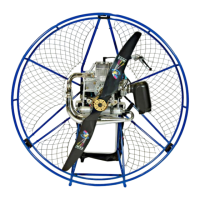
Fig. 12 - slide attack
Ensure that the harness is
attached correctly to the
distance bars as shown in
fig. 12, and then insert
them into their frame seats
as shown in Fig. 13.
Fig. 13 - central connect
Fig. 15 Bottom straps
Next, attach the two
bottom of the harness
straps as shown in Fig. 15
Fasten these belts securely
as in fig. 16.
Do this for the left and
right sides. Leave these
straps at their loosest
setting for now, we’ll
adjust them later.
Fig. 16 mounting straps
DISTANCE BARS:
These distance bars are extremely easy to mount and dismount since they slide easily into the
central frame. The end of the distance bars are made of a square aluminium profile that does
not allow them to rotate. Due to the compression of the harness, the distance bars can not slide
out of their fittings during flight.
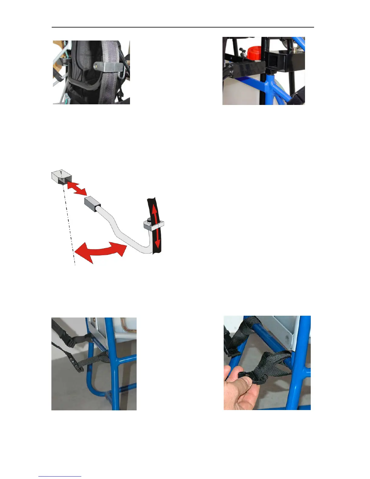
Fig. 14 Distance bar system.
ANTITORQUE SISTEM
The distance bars are designed to favour the
sliding of front harness webbing in a way that the
pilot finds the proper angle with the paraglider.
With this system the discharge of the propeller
torque onto the risers is avoided, which usually
gives the the tendency to turn one direction that in
the case of the rotation of the G24 engine the
tendency is to turn right.
LATERAL WIDENING OF DISTANCE BARS.
The distance bars allow a lateral movement which is useful for the pilot to enter easily into the
harness.
 Loading...