2
BASIC SENSOR CONNECTIONS
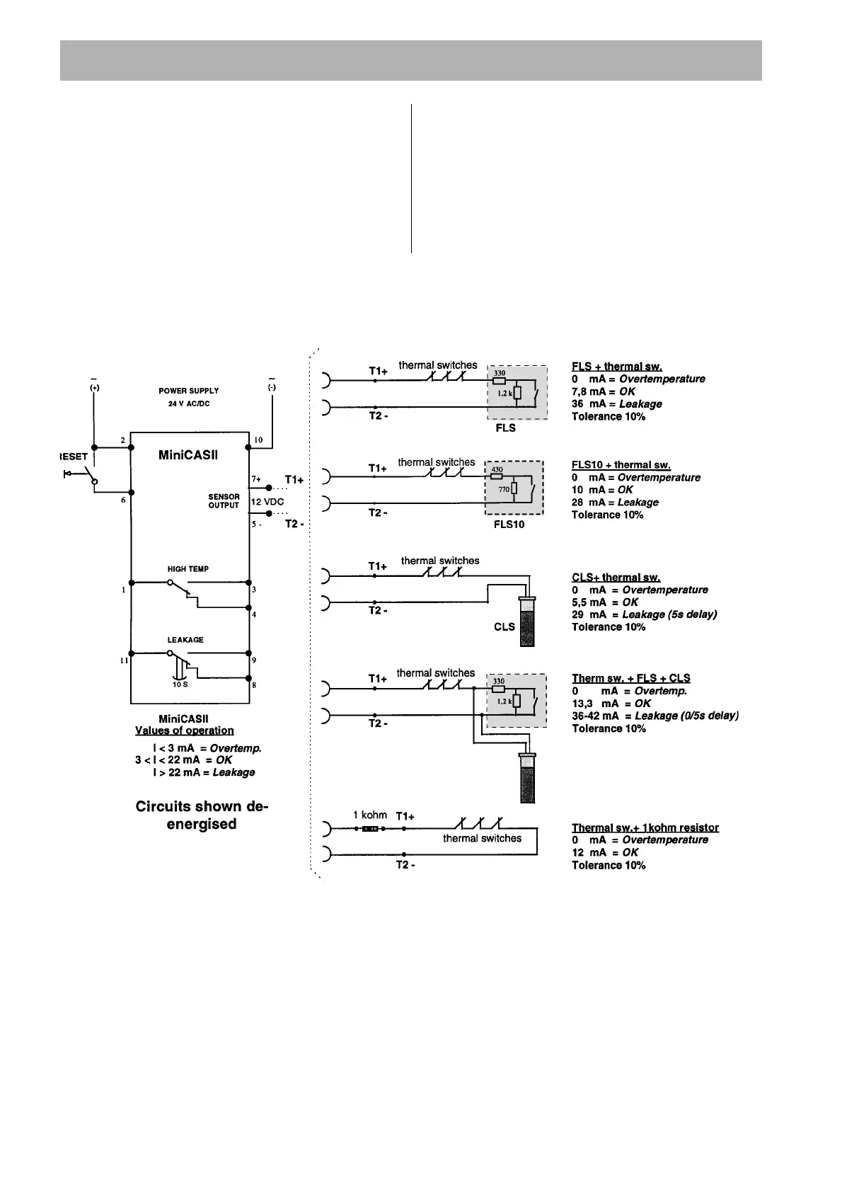
(5 alternative sensor combinations)
INTRODUCTION
A number of condition monitoring sensors are
available for the ITT FLYGT pump range.
• Thermal switches for stator overtemperature.
• CLS for water in oil detection.
• FLS for the detection of liquid in the stator housing.
• FLS10 for detection of liquid in the inspection
chamber in the new midrange pump series, eg
3153, 3171 and 3202.
Any combination of these sensors can be used with
the standard versions of the pumps. Explosion proof
approved pumps are restricted to the use of the
thermal switches with or without FLS and FLS10 only.
The sensors are monitored by the ITT FLYGT
MiniCAS II supervision relay, which is situated in the
panel.
NOTES
1. Amber LED indicates supply on.
— Overtemperature relay energised when healthy.
— Leakage relay de-energised when healthy.
— Red overtemperature LED off when healthy.
— Red leakage LED off when healthy.
2. MiniCAS II resets automatically after leakage fault.
MiniCAS II requires resetting after overtemperature
fault. Please see ”Technical Data”.
3. There is not a separate indication when two
leakage sensors are used.
(1)
(2)
(3)
(5)
(4)
CLS