3
INSTALLATION
The monitoring connections at the panel
The MiniCAS II supervision relay is installed in the
pump panel and simply plugs into an eleven pin relay
base. Six basic sensor connections are possible.
1. Thermal switches with FLS
The pilot cores in the pump can be connected to
the panel in either polarity.
2. Thermal switches with FLS10
The pilot cores in the pump can be connected to
the panel in either polarity.
3. Thermal switches with CLS
The CLS sensor is diode protected. For this reason
the pilot cores are required to be connected with
the correct polarity (brown = +, black = –). Connect-
ed incorrectly the MiniCAS II supervision relay will
indicate an open circuit (0 mA), i.e. with the amber
supply LED and the red overtemperature LED both
on. Connected correctly and reset, the amber LED
only will be on.
4. Thermal switches with CLS + FLS
The pilot cores in the pump cable are required to
be connected with the correct polarity (brown = +,
black = –), however, because the FLS will cause
the MiniCAS II to indicate healthy, i.e. amber LED
ON, even when incorrectly connected CLS, a cur-
rent reading of the monitoring circuit must be taken
when installing the pump. Correct polarity will indi-
cate 15.0 mA; incorrect polarity will indicate 7.8 mA
with healthy conditions.
5. Thermal switches only
A 1000—1500 ohm resistor must be connected in
series with the thermal overtemperature switches.
A 1000 ohm resistor is enclosed in the package.
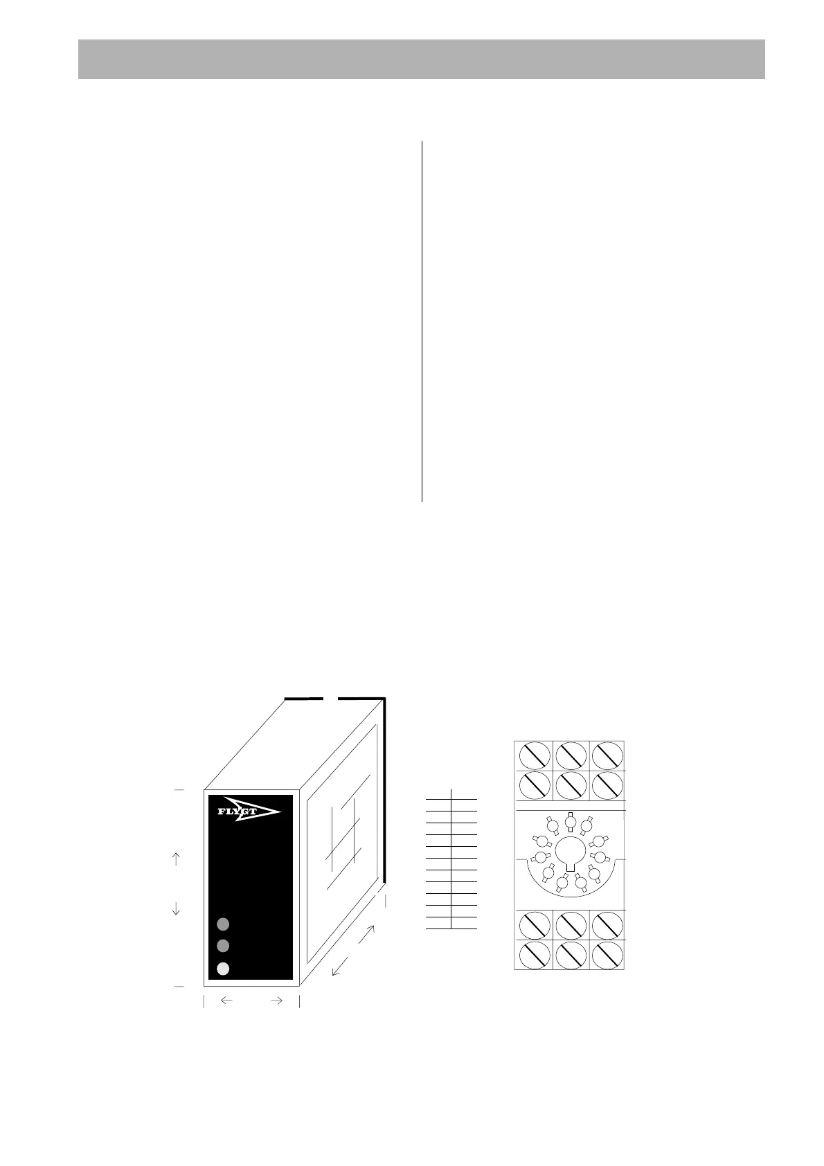
Top
MINI
Control
And
Status
II
79mm
33mm
LEAKAGE
TEMPERATURE
SUPPLY
75mm
Part-no.: 84 55 67
EN 50042
111
2A1
314
412
522
621
724
832
934
10 A2
11 31
MiniCAS II supervision relay 11 pin relay base
 Loading...