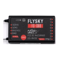
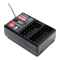
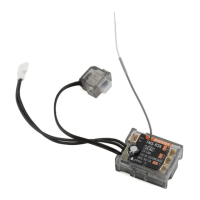
FS-SR8
接收机 Receiver
http://www.flysky-cn.com
Copyright ©2024 Flysky Technology Co., Ltd.
对码
Binding
本款接收机支持双向对码和单向对码 ,双向
对码完成后发射机将显示接收机回传的信
息。
双向对码步骤:
1. 发射机选择双向通信,然后进入对码状
态;
2. 本接收机支持三种方式进入对码状态:
按键对码、对码线对码和通电后按键对
码
• 按键对码:按住接收机对码按键同时
上电,接收机 LED 灯快闪表示进入对
码状态,松开对码键;
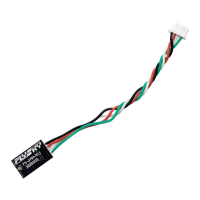
• 对码线对码:BIND 接口连接对码线
后上电,接收机 LED 灯快闪,进入对
码状态。注意对码成功后需取下对码
线;
• 通电后按键对码:接收机上电后未与
发射机通信过,长按对码键 3 秒,接
收机指示灯快闪表示进入对码状态,
松开对码键。
3. 接收机 LED 灯常亮,即对码成功(发射
机对码成功后自动退出对码状态);
4. 检查发射机、接收机是否正常工作。如
需重新对码,请重复以上步骤。
单向对码步骤:
1. 发射机选择单向通信,然后进入对码状
态;
2. 本接收机进入对码状态(进入对码状态
的方式请参考双向对码时描述);
Thereceiversupportstwo-waybindingandone-waybinding.Thetransmitter
willdisplaytheinformationreturnedfromthereceiverafterthetwo-way
bindingiscompleted.
Followthestepsbelowtobindintwo-waybinding:
1. Set 2WAY for RF standard of the transmitter, then put the transmitter into
bind mode.
2. The receiver supports three ways to enter bind mode: BIND button binding,
bind cable binding and BIND button binding after power-on.
• BIND button binding: Press and hold the BIND button of the receiver
while powering on the receiver, the LED of the receiver should be ashing,
indicating that the receiver is in bind mode. Then release the BIND button.
• Bind cable binding: Insert the bind cable to the BIND connector of the
receiver, then power on the receiver. The LED of the receiver should be
ashing, indicating that the receiver is in bind mode. Note that you need
to remove the bind cable from the receiver after the binding process is
completed.
• BIND button binding after power-on: The receiver has not been connected
to the transmitter when it is powered on. Press and hold the BIND button
for 3 seconds, the LED of the receiver should be ashing, indicating that
the receiver is in bind mode. Then release the BIND button.
3. When the LED of the receiver is solid on, the binding process should be
completed. The transmitter exits the bind mode automatically.
4. Check to make sure the transmitter and receiver functions are working
correctly, repeat steps 1 to 3 (binding process) if any problems arise.
Followthestepsbelowtobindinone-waybinding:
1. Set 1WAY for RF standard of the transmitter, then put the transmitter into
binding mode.
2. Put the receiver into binding mode (Refer to the description above for
entering bind mode).
3. After the receiver LED becomes slow ashing, then put the transmitter to exit
PWM 转换器
PWM Converter
收机 LED 灯状态变为 1 闪 1 长亮 1 长灭时,
松开对码按键,即将接收机设置为 PWM 转
换器。与接收机输出 i-BUS 或 S.BUS 的接口
连接后即可扩展输出通道。
注:PWM 转换器识别到输入信号,LED 状
态为 1 闪 1 长亮。
PWM 转换器连接
连接方式:
• 与 ANT 协议的接收机连接:将 PWM 转
换器的 SENSE 接口与接收机的 SERVO
接口连接。
• 与 AFHDS 3 协议的接收机连接:将
PWM 转换器的 SENSE 接口与接收机输
出 i-BUS-OUT 或 S.BUS 接口连接。
• 其他非富斯接收机:将 PWM 转换器的
SENSE 接口与接收机输出 S.BUS 接口连
接。
注:PWM 转换器接口不支持连接 PWM 转换
器实现通道扩展。
PWM 转换器 PWM 接口输出信息
• PWM 转换器连接的接收机通道数不大于
8 个通道:PWM 转换器标识为通道 1 的
接口输出发射机的通道 9,通道 2 输出发
射机的通道 10,以此类推,通道 8 输出
发射机的通道 16。即 PWM 转换器固定
输出发射机通道 9- 通道 16。
• PWM 转换器连接的接收机通道数大于 8
个通道:接收机 9 通道及之后的通道与
PWM 转换器的通道相关联,即重叠的通
道输出相同。
andlessthan10seconds,untilthereceiverLEDstatuschangestoFlash-once,
ON-once,andOFF-oncestate,releasetheBINDbutton,andthereceiverhas
beensettoaPWMconverter.Afterconnectingtotheconnectorofthereceiver
thatoutputsi-BUSorS.BUSforchannelexpansion.
Note: When the PWM converter recognizes the input signal, the LED operates in
Flash-once and ON-once state.
PWM Converter Connection
ConnectionMethod:
• ConnectionwithreceiverofANTprotocol:ConnecttheSENSEconnectorof
PWMconvertertotheSERVOconnectorofreceiver.
• ConnectionwithreceiverofAFHDS3protocol:ConnecttheSENSE
connectorofPWMconvertertotheconnectorofreceiverthatcanoutput
i-BUS-OUTorS.BUS.
• Othernon-FlySkyreceivers:ConnecttheSENSEconnectorofPWM
convertertotheconnectorofreceiverthatcanoutputS.BUS.
Note: PWM converter does not support channel expansion by connecting PWM
converter.
Output Information of Connectors for PWM Converter
• ThenumberofreceiverchannelsconnectedbythePWMconverteris
notmorethan8channels:Theconnectormarkedaschannel1ofPWM
converteroutputschannel9oftransmitter,channel2outputschannel10
oftransmitter,andsoon,channel8outputschannel16oftransmitter.That
is,PWMconverteroutputstransmitterchannel9-channel16andcannotbe
set.
• ThenumberofreceiverchannelsconnectedbyPWMconverterismorethan
8channels:receiverchannel9andsubsequentchannelsareassociated
withthechannelsofPWMconverter,theoverlappingchannelshavethe
sameoutput.Namely,thechannel9ofthePWMconverterandthereceiver
channel9havethesameoutput.
 Loading...