Issue/Rev. 0.2 (7/00)
Page 1
Bulletin MNIS005
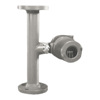
Model WCM 7300
October 2000
INVALCO
Installation/Operation Manual
Water Cut Monitor with
Temperature Compensation
Table of Contents
General Overview..............................................................................................................................2-3
Specifications and Definitions...............................................................................................................................3
Error Messages...............................................................................................................................................4
Product Temperature Compensation.........................................................................................................................4
Set Point and Loop Calibration......................................................................................................................5
Program Flow Chart..........................................................................................................................................5
Quick Steps....................................................................................................................................................6
Programming of WCM 7300 ....................................................................................................................7
Installation..................................................................................................................................7
Electrical Connections.......................................................................................................................................8
Trouble Shooting............................................................................................................................................9-10
Dimensions...............................................................................................................................11
FMC INVALCO ■ Fluid Control ■ P.O. Box 1377 ■ Stephenville, Texas 76401 ■ Telephone: 254/968-2181 ■ FAX 254/968-5709 ■ Toll Free: 800/468-2526