www.fmiproducts.com
108998-01G6
MODELS WITH STAMPED FACE LOUVERS
(B36, VB36 WOOD BURNING UNITS)
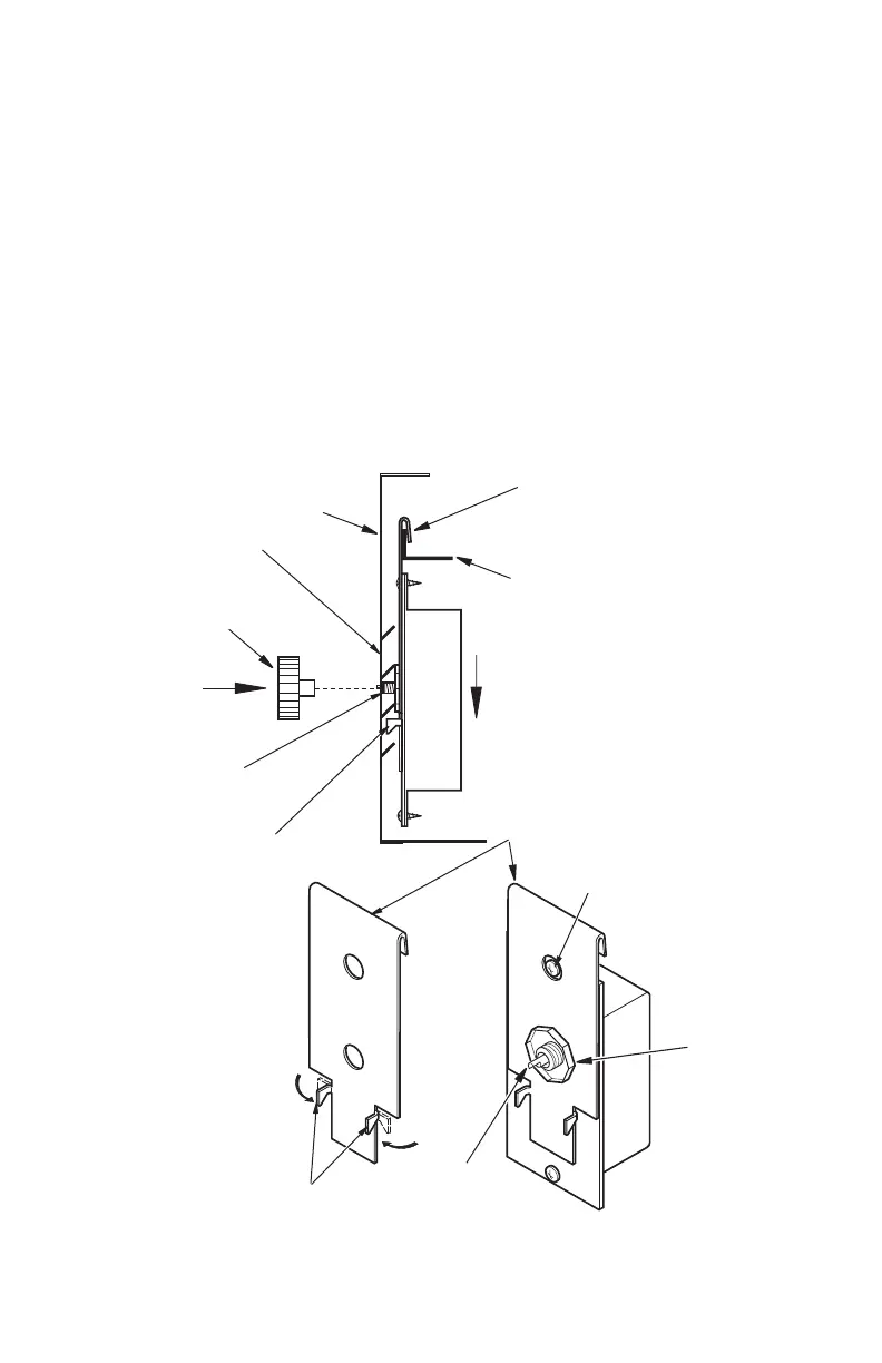
Using pliers, bend two retaining tabs on 1.
speed control bracket 90 degrees to front
of bracket (see Figure 9).
Mount speed control box by placing 2.
plastic control shaft through bottom hole
on speed control bracket. Top screw
head on control box will t inside top
hole on bracket (see Figure 9). Secure
speed control to bracket with lock nut
by pushing and turning lock nut with
pliers clockwise until it is tight against
bracket.
Remove knockout plug from louver panel 3.
by depressing top and bottom retaining
clips (see Figure 1, page 2).
Position speed control assembly over 4.
ange on hearth pan by sliding bracket
up between the face and ange, then
down until the control shaft is aligned
with the opening in the louver panel
(see Figure 9).
Lock two retaining tabs onto lower louver 5.
by pressing down on bracket assembly
while sliding control knob through rect-
angular opening on louver and onto the
control shaft (see Figure 9).
Speed Control
Bracket with
Assembly
Srew Head
and Top Hole
on Bracket
Control
Shaft
Control Shaft
Hearth Pan
Flange
Firebox Face
Speed
Control
Bracket
Retaining
Tabs
Retaining Tab
Control Knob
Louver Panel
Lock Nut
Figure 9: Attaching Speed Control to Firebox with Stamp Faced Louvers (B36 and
VB36 Models) Using Speed Control Bracket 109892-01
MOUNTING SPEED
CONTROL
Continued
 Loading...