Do you have a question about the Fnirsi SG-003A and is the answer not in the manual?
Detailed technical specifications for various signal outputs and inputs, including range and precision.
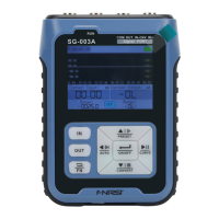
Overview of key functions like signal conversion, programming output, and real-time curve display.
Description and function of the device's input and output connection ports.
Information regarding the instrument's battery, charging port, and charging status indicators.
Guide on how to change between different input and output signal types.
Details on configuring and using mA current output signals, including protection and range.
Instructions for V voltage signal configuration, covering protection and output range settings.
Configuration options for passive current signals, including mode and output range.
Comprehensive guide to pulse signal generation, including frequency, PWM, speed, and counting modes.
Explanation of the 24V loop detection function for testing and power supply applications.
Converting analog signals to engineering units by defining signal and unit limits.
Setting and utilizing preset signal values for quick adjustments and common outputs.
Process of converting input signal types and ranges to desired output signals.
Automated, cyclical signal output based on programmed parameters for testing.
Displaying and analyzing signal trends using real-time graphical curves.
Setting parameters for automatic output termination based on time expiration.
Establishing communication via USB and configuring Modbus slave addresses.
Troubleshooting common instrument malfunctions and error conditions.
Guidelines for proper care and maintenance of the signal generator to ensure longevity.
Step-by-step instructions for updating the device's firmware via USB.
| Model | SG-003A |
|---|---|
| Type | Signal Generator |
| Display | LCD |
| Bandwidth | 10MHz |
| Channels | 1 |
| Display Type | LCD |
| Output Waveforms | Sine, Square, Triangle |
| Amplitude Range | 0 - 10Vpp |
| Power Supply | USB or 3.7V Li-ion battery |
| Operating Modes | Continuous |
| Application | Testing |
| Power | USB or 3.7V Li-ion battery |
| Frequency Range | 1Hz - 10MHz |