5
IMPULSE 4.320 aMPLIfIEr
User manual
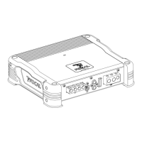
Installing your IMPULSE 4.320 amplifier
Installation of this product requires technical knowledge and experience. If you are uncertain of your ability to
correctly install the amplifier, we strongly recommend you contact your Focal dealer who will install it for you, so
that you will be able to take full advantage of the full capabilities of your IMPULSE 4.320 amplifier.
Wiring your IMPULSE 4.320 amplifier
Only use the wiring harnesses recommended in this manual and the accessories supplied.
Use the ISO cable (sold separately) to facilitate wiring. The speaker driver cable must ONLY be used for connecting
the amplifier to the speaker drivers. The wire gauge of power cables must correspond with those indicated in the
table (paragraph 3.1) and depends on the power of your amplifier and the length of cable required. Use double or
triple shielded RCA cables to avoid any interference of the low-level signal.
Operating time of your IMPULSE 4.320 amplifier
Avoid using the amplifier for extended periods of time without starting the vehicle. This may cause the battery to run
flat prematurely.
Cooling system
Do not cover the top of your IMPULSE 4.320 amplifier as this may cause overheating.
Materials required for installation (in addition to accessories supplied)
• 2 sheaths of adequate cross-section (1 sheath for the power cable, 1 sheath for the speaker driver, REMOTE and
RCA modulator cables)
• Multimetre (voltage/amperage)
• Soldering iron + solder
• Crimpers
• Wire stripper
• Wire cutter
• Battery terminal spanner
• Hand drill and assorted drill bits
• Heat-shrink tubing of adequate diameter for the different cables
• Power cable of adequate length and wire gauge
• Remote turn-on cable (REM input on amplifier) of adequate length and wire gauge
• Ground cable of suitable length and wire gauge
• Fuse holder and suitable fuse
• Spade terminal for connecting to positive (+) battery terminal
• Spade terminal for connecting to the chassis of the vehicle (-).
• Screw with minimum 0
15⁄64
" (6mm) screw head and its nut for ground connection to the chassis of the vehicle
Installation
The following section deals with issues related to the vehicle which must be considered for before installing your
amplifier. You will save time by planning the layout of the system and wiring in advance.
During this preparatory time, please ensure that all the settings remain accessible once the installation is complete.

 Loading...