Do you have a question about the Foif OTS685-R500 and is the answer not in the manual?
Safety guidelines for instrument handling, environmental conditions, and battery maintenance.
Defines WARNING and CAUTION symbols used in the manual for safety.
Specifies safety standards and precautions for laser usage.
Information on the battery power symbol, usage, and maintenance.
Step-by-step instructions for removing and installing the instrument battery.
Detailed procedure for charging the instrument's battery.
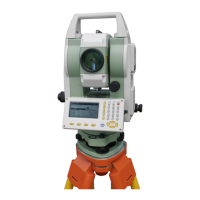
Instructions for correctly setting up the instrument on a tripod.
Guides for centering the instrument and achieving proper leveling.
Comprehensive guide to setting various instrument parameters.
Configures parameters related to measurement conditions.
Sets fundamental parameters for instrument operation.
Configures communication parameters for data transfer.
Configures settings specific to the EDM (Electronic Distance Measurement).
Steps to measure the horizontal angle between two sighted targets.
Procedure to set a specific horizontal angle value.
Procedures and notes for performing distance measurements.
Entering initial station and instrument setup coordinates.
Setting the backsight azimuth for orientation.
Measuring and calculating 3D coordinates of targets.
Determining station coordinates by measuring known points.
Determining station elevation by measuring known points.
Process of defining a baseline for line stake out operations.
Staking out a specific point relative to a baseline.
Staking out a point relative to a defined line.
Procedure for staking out an arc defined by two points and a radius.
Procedure for staking out an arc defined by three points.
Defining the starting point and parameters for road layout.
Defining horizontal elements like lines, curves, and spirals.
Defining vertical alignment elements for the road.
Explanations and solutions for common instrument warnings and errors.
Calibrating the tilt sensor to ensure accurate leveling.
| Brand | Foif |
|---|---|
| Model | OTS685-R500 |
| Category | Measuring Instruments |
| Language | English |