Do you have a question about the Foif RTS680 Series and is the answer not in the manual?
General safety notes covering sun collimation, handling, and temperature.
Defines WARNING and CAUTION symbols used to prevent injury or damage.
Details laser safety standards, including Class 3R and Class 1 classifications.
Specifies user requirements and the need for protective gear during operation.
Outlines manufacturer's non-liability for misuse, damage, or data loss.
Explains the battery power symbol and provides notes on battery usage and maintenance.
Step-by-step instructions for mounting the instrument on a tripod.
Details the process of centering the instrument and achieving level status.
Describes using the electronic level on screen for precise instrument leveling.
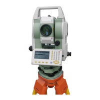
Identifies and labels the various parts of the total station instrument.
Explains the function of each key on the instrument's keypad and soft keys.
Describes the information shown on the instrument's LCD screen.
Illustrates the instrument's operational modes and the flow between them.
Covers instrument power operations and the initial registration or demo mode.
Comprehensive guide to configuring instrument parameters like measurement conditions and units.
Procedure for measuring the horizontal angle between two sighted points.
Instructions to set the horizontal angle to a predefined value or azimuth.
Step-by-step guide for performing distance measurements using the instrument.
Guide for entering the instrument's occupied point coordinates and heights.
Procedure for setting the backsight azimuth, either by calculation or direct input.
Steps to measure and calculate the 3D coordinates of a target point.
Method for staking out a point based on a specified distance and direction.
Process for staking out points using pre-defined coordinates.
Determining the instrument's position by measuring known points.
Calculating the instrument's elevation using known points.
Important precautions and desirable point arrangements for accurate resection.
Inputting the starting station and coordinates for road layout design.
Defining the horizontal alignment of the road with lines, curves, and spirals.
Inputting the vertical profile of the road, including grades and elevations.
Performing calculations for road design, width, and staking points.
Executing the stakeout process for defined road points.
Options for selecting internal memory or external SD card for data storage.
Procedure for selecting the active job and coordinate search job.
Steps for deleting existing jobs and their associated data.
Instructions for downloading job data from the instrument to a PC.
Manually entering coordinates for known points using the instrument's keypad.
Process for deleting specific known point coordinate data.
Steps to clear all entered known point data from the active job.
Procedure to check and calculate the instrument's constant.
Steps for checking and adjusting the tubular leveling bubble.
Steps for checking and adjusting the circular leveling bubble.
Calibrating the tilt sensor to ensure accurate angle measurements.
Correcting the vertical index error for accurate vertical angle readings.
| Category | Total Station |
|---|---|
| Distance Measuring Time (Fine) | 1.2s |
| Telescope Magnification | 30X |
| Field of View | 1°30' |
| Battery Type | Li-ion battery |
| Angle measurement method | Absolute Encoding |
| Angle Minimum Display | 1" |
| Distance Measurement (Prism) | 5000m |
| Distance Accuracy (Prism) | ±(2mm + 2ppm×D) |
| Distance Accuracy (Reflectorless) | 3mm+2ppm |
| Data Storage | Internal memory |
| Communication | USB, Bluetooth |
| Operating Temperature | -20°C to +50°C |