Do you have a question about the Foif OTS682-R500 and is the answer not in the manual?
General safety guidelines for instrument operation and handling.
Explains symbols like WARNING and CAUTION for user safety.
Details laser safety standards and precautions for the OTS series.
Provides information on the battery, its symbol, replacement, and charging.
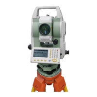
Instructions on how to properly set up the instrument on a tripod.
Steps for accurately centering and leveling the instrument using the plummet and levels.
Configures measurement parameters like distance mode, tilt, and units.
Adjusts fundamental instrument settings such as auto-off and contrast.
Sets communication parameters for connecting the instrument to a computer.
Configures Electronic Distance Measurement (EDM) parameters like mode and prism.
Procedure to measure the horizontal angle between two sighted points.
Sets a specific horizontal angle as a reference or target.
Enters the instrument's starting position coordinates and heights.
Sets the backsight azimuth by calculation or direct input.
Calculates and displays target point coordinates using measured data.
Stakeout based on horizontal angle and distance from the instrument.
Stakeout using pre-defined coordinates for the target point.
Stakeout for points inaccessible for direct measurement, using remote elevation.
Determines instrument station coordinates by measuring known points.
Determines instrument station elevation using known points.
Defines a baseline by inputting coordinates of two points.
Stakeout of a point based on length and offset from a baseline.
Stakeout relative to a baseline and a connected line, indicating offline and cut/fill.
Measures and saves foresight point coordinates for traverse calculations.
Uses saved coordinates as the new occupied or backsight point.
Manages JOBs, including selecting active and search JOBs, and setting scale factors.
Calibrates the tilt sensor to cancel zero point errors.
Checks and corrects the vertical index error of the instrument.
| Brand | Foif |
|---|---|
| Model | OTS682-R500 |
| Category | Measuring Instruments |
| Language | English |