8
1
2
3
4
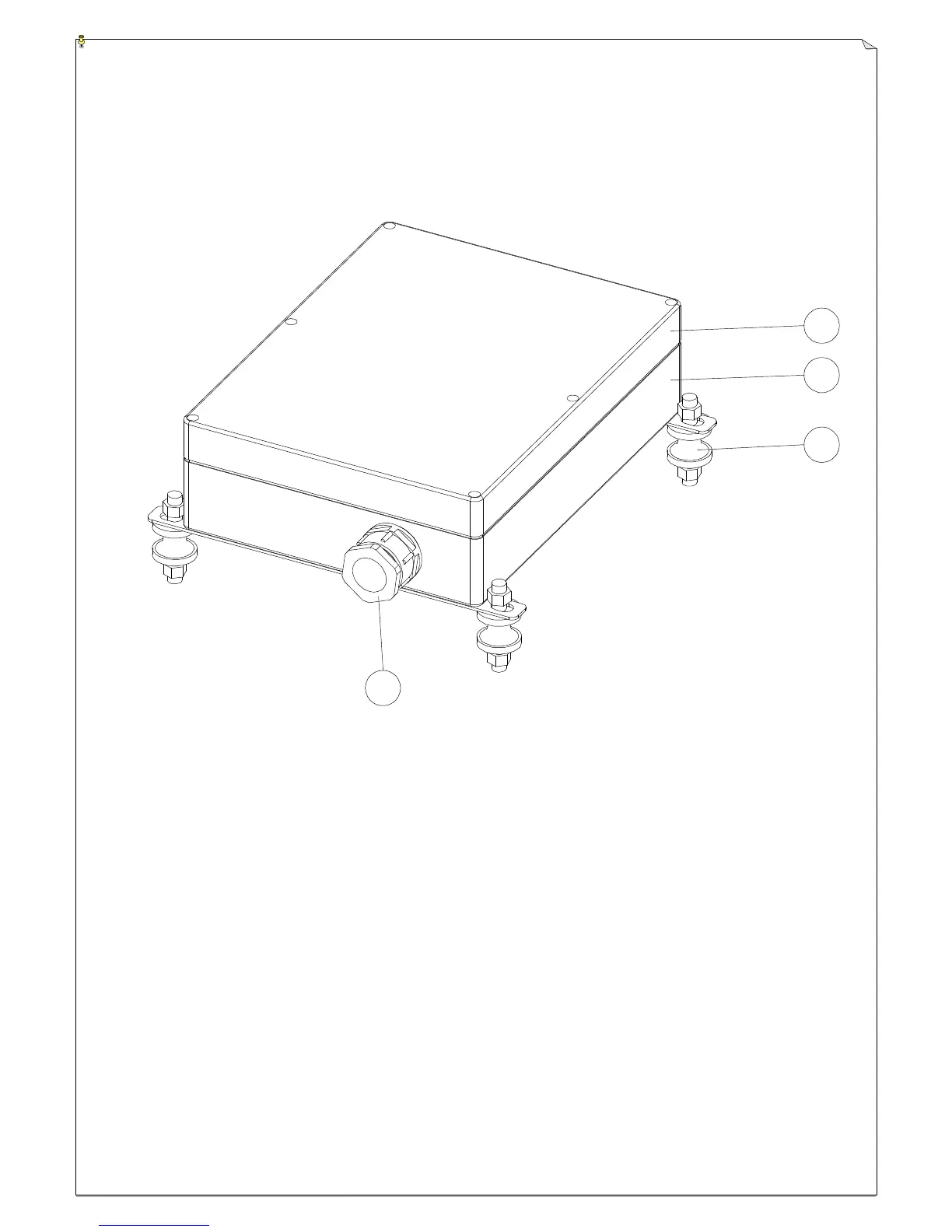
(Fig. 7) Receiver External Assembly
1) Transparent top cover 3) Mounting bracket with shock absorbers
2) Light-gray colored base 4) Cable gland (PG-29)
* POWER ~ AC Power Source Indicator “On" AC input power supplied.
“Off” No AC input power.
* SQ ~ RF Signal Indicator "On" RF signals received.
"Off" No RF signals received.
* RELAY_COM ~ DC Power Source to Relays “On” DC power to relays.
“Off” No DC power to relays.
* STATUS ~ Receiver System Status LED Display Please refer to page 14.




 To Next Page