9. Resetting to Default
The UNITY indicator light goes off when the setting value
is changed from the default value. Pressing the UNITY
button while the light is off returns the corresponding
setting value to the default value. Then the light goes off.
Pressing the button again returns the value to the previous
value before resetting to the default value.
* The above procedure is in NORMAL mode. Normally the
unit starts up in NORMAL mode. There is another mode
called LIVE SAFE mode, in which some menus request a
setting change confirmation to protect important settings
from accidental changes. If the unit is in LIVE SAFE
mode, see sec. 4-2-7. “Resetting to Default” in the
FA-9500 Operation Manual.
Precautions
Operate the unit only at the specified supply
voltage.
Ensure the unit is properly grounded at all times.
Ensure the power cord and connectors are firmly
connected.
Do not access circuitry with power applied to the
unit.
Unit should not be operated or stored with the
cover, panels, and/or casing removed.
Unit should not be operated or stored in a
humid, dusty, etc. environment. Doing so could
result in fire or electrical shock.
Do not allow fluids, metal fragments, or any
other foreign objects to enter the unit. If foreign
matter does enter the unit, turn the power off and
disconnect the power cord immediately. Remove
the material or contact your authorized service
representative
If you notice any strange smells or noises coming
from the unit, turn the power off immediately, turn
OFF the power switch, disconnect the power
cord, then contact your authorized service
representative.
● SDI REMAPPING
SDI MONO SUM
AES HYSTERESIS
● AES REMAPPING
CONV1 SIZE/POS
CONV1 CROPPING
ANALOG IN GAIN
ANALOG OUT LEVEL
ANALOG OUT GAIN
ANALOG MONO SUM
● ANALOG SYSTEM
● CONV2 U/D MODE
CONV2 SIZE/POS
CONV2 CROPPING
CONV2 IMPROVE
CONV2 SIDE RGB
● SD INPUT ASPECT
CHGOV(CHANGEOVER) MODE
SET
*2
SDI ERROR TRG
*2
FORMAT ERROR TRG
*2
CRC ERROR TRG
*2
BLACK VIDEO TRG
*2
AUDIO LOSS TRG
*2
SILENCE TRG
*2
CHGOV STATUS
*2
CHGOV VID STATUS
*2
CHGOV AUD STATUS
*2
AUD LOSS STATUS
*2
AUD ERROR STATUS
*2
SILENCE STATUS
*2
● DOWN MIX SET
● DOWN MIX ASSIGN
● VIDEO OUT MODE
● SDI1/2 OUT SET
● SDI3/4 OUT SET
● COMPOSITE SET
● COMPONENT SET
*5
● Dolby AUX OUT
*3
● Dolby DEC INPUT
*3
● Dolby DEC REF
*3
● Dolby DOWNMIX
*3
Dolby DEC GAIN
*3
● Dolby ENC INPUT
*4
● Dolby ENC SET
*4
● METADATA INPUT
*4
LOUD MEASURE 1, 2
*6
LOUD CTRL ENA1, 2
*6
LOUD CTRL SET1, 2
*6
LOUD CH ASGN1, 2
*6
LOUD STANDARD
*6
● FS MODE SET
FREEZE SET
COMPOSITE SET
● VIDEO SUB
● TEST SIGNAL
HD PHASE SET
SD PHASE SET
VIDEO POSITION
● CONV1 ANC SET
● CONV2 ANC SET
CONV1 AUDIO GRP
CONV2 AUDIO GRP
SD LINE MASK
ANC DETECT LINE
ANC DETECT SEL
ANC DATA EMBED
ANC EMBED LINE
ANC LOSS SET
WSS AFD ERROR
NTSC SETUP
*5
● PAL-M MODE SET
● DIGITAL AUDIO
● AUDIO ERR SENSE
● DIGITAL SILENCE
UNIT ALARM
VIDEO IN STATUS
COMPONENT INPUT
*5
VIDEO OUT STATUS
COMPONENT OUTPUT
*5
SOURCE AUDIO CH1 – 16
SDI1 IN AUDIO CH1 – 16
SDI2 IN AUDIO CH1 – 16
AES IN AUDIO CH1 – 8
ANALOG IN AUDIO CH1 – 4
SDI1/2 OUT AUDIO CH1 – 16
SDI3/4 OUT AUDIO CH1 – 16
AES OUT AUDIO CH1 – 8
ANALOG OUT AUDIO CH1 – 4
Dolby AUX STATUS
*3
AFD IN STATUS
ANC IN STATUS
ANC IN STATUS1-2
CONV1 ANC OUT
CONV1 S2016 OUT
CONV1 VI OUT
CONV1 WSS OUT
CONV1 ANC OUT1
CONV2 ANC OUT
CONV2 S2016 OUT
CONV2 VI OUT
CONV2 WSS OUT
CONV2 ANC OUT1
FRONT OPERATION
FRONT PANEL SET
GPI SETTING
NETWORK INFO
UNIT Ver.
OPTION A Ver.
OPTION B Ver.
OTHER OPTION
SOFT OPTION1
SOFT OPTION2
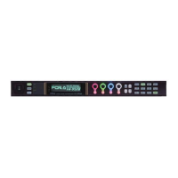
① Select VIDEO or AUDIO by the VIDEO /AUDIO button.
Every press of the VIDEO/AUDIO button alternates the menu button
assignments between video and audio menus. The button indicators
light green when the buttons are accessible to video menus that are
indicated on the top row of each menu button. They light orange when
they are accessible to audio menus that are indicated on the bottom
row of each menu button.
② Press a menu button to select a menu group that includes the desired
menu.
③④Move to the desired menu using double-arrow and/or single-arrow
buttons.
The single-arrow buttons allow you to move between menus if the
selected menu button has multiple menu pages in the category. The
single-arrow button lights up when there are more menus to be
accessed in the direction. If the single-arrow button is unlit, the
direction is not accessible.
The double-arrow buttons allow you to go to menus indicated with
in the menu list.
⑤ F1 to F4 control knobs allow you to change the value of respective
lines. Turn the operative control knob of an LED that is lit to change the
value.
<Comments on the menu list>
Can be navigated to using double (up and down) arrow buttons. “ “ is not
shown in the menu display.
● When settings in menus shown with a black circle (●) are changed in LIVE SAFE
mode, single (up and down) arrow buttons and the LED around the control knob
of which setting is changed blink confirming the setting change. To set the
FA-9520 to LIVE SAFE mode, change the mode setting referring to section 7-3.
“FRONT OPERATION”.
*1 Hidden if the optional FA-95DACBL is installed.
*2 Shown if the optional FA-95CO is installed.
*3 Shown if the optional FA-95D-D is installed.
*4 Shown if the optional FA-95DE-E is installed.
*5 Shown if the optional FA-95AIO is installed.
*6 Shown if the optional FA-95ALA is installed.
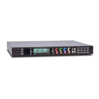
F1
F2
F3
F4
UNITY UNITY UNITY UNITY
Press the UNITY button to reset the value. The
indicator lights up orange.
F1
F2
F3
F4
UNITY UNITY UNITY UNITY
F1-F4 change setting values in corresponding
lines.
FA-9500
HD/SD FRAME SYNCHRONIZER
F1
F2
F4
F3
① VIDEO/AUDIO button
VIDEO menus (lit green)
AUDIO menus (lit orange)
④ Single-arrow button
Moves to the next menu.
Lights if a menu is accessible.
Goes off if no menu is accessible.
Also used to move to the next
menu item in a menu page.
② Menu button
Jumps to the first menu of
each menu group
indicated on respective
menu buttons.
③ Double-arrow button
Jumps to the first menus
corresponding to each
menu button.
⑥ F1 to 4
Changes corresponding
line menu parameters.
MASTER
CONV2
OUT SEL
MODE
VIDEO
AUDIO
ANALOG
CONV1
IN SEL
DOWNMIX
STATUS
OTHER
C C
AES AUDIO
CLIP
DELAY
AUDIO SYS
VIDEO SYS
AUDIO OP
VIDEO OP
MAPPING
A V O
PROCESS
SDI AUDIO
F4
UNITYUNITYUNITYUNITY
F3
F2
F1
F A - 9 5 0 0
DISPLAY AREA
HD / SD F R A M E SY S N C HR O N IZ E R
VIDEO IN
AUDIO IN
GENLOCK
REMOTE
FAN ALARM
DC POWER
BY-PASS
LOCK
EVENT
ON
OFF
POWER
F1
F2
F3
F4
 Loading...