Page 2 of 8
ENG-0091.3
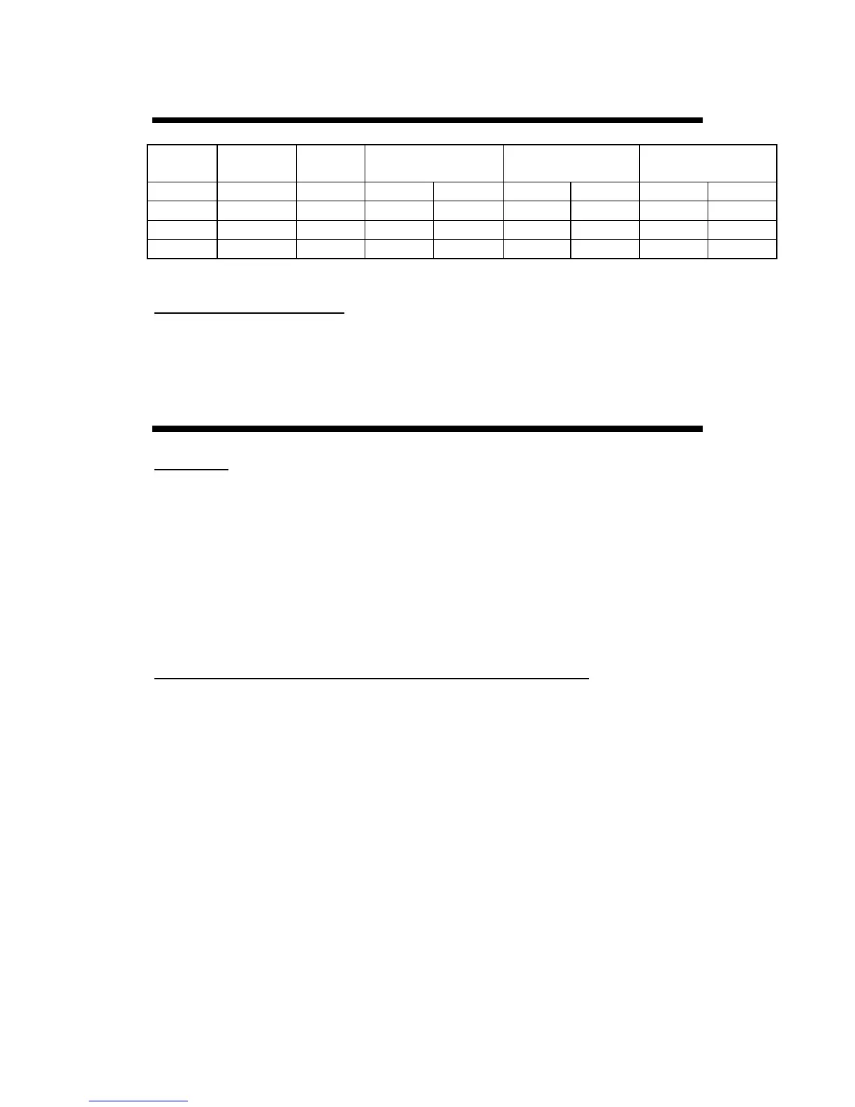
ELECTRICAL REQUIREMENTS
Model Voltage Freq. Surface Element
(each)
Oven or Broiler
Element
Maximum
65335 100 - 120 50 - 60 1200 W 10 A 1300 W 10.8 A 4900 W 41 A
75331 100 - 120 50 - 60 1200 W 10 A 1300 W 10.8 A 4900 W 41 A
65336 200 - 250 50 - 60 1200 W 5 A 1300 W 5.4 A 4900 W 20.4 A
75332 200 - 250 50 - 60 1200 W 5 A 1300 W 5.4 A 4900 W 20.4 A
Recommended Breaker Size
120 Volt units – 50A
240 Volt units – 30A
INSTALLATION
Unpacking
1. Remove all plastic coating before use.
2. Please copy the Model and Serial number of your unit into your manual. This is
located both on the box and the right side of the Range.
MODEL #_________________ SERIAL #___________________
Minimum Clearances to Adjacent Walls and Overhead Cabinets
No Clearance is required to an adjacent wall.
30" (762mm) minimum clearance between the top of the cooking surface and the
bottom of an unprotected wood or metal cabinet;
or
24” (610mm) minimum when bottom of wood or metal cabinet is protected by a
flame retardant heat shield.
To eliminate the risk of burns or fire by reaching over the heated surface, cabinet
storage space located above the surface units should be avoided. If cabinet storage is
to be provided, the risk can be reduced by installing a range hood that projects
horizontally a minimum of 5" beyond the bottom of the cabinets