23
FORCE E
Installation, Operating & Service Manual
109444-03 - 12/19
10 Operation (continued)
v. Check pilot flame. It must be blue,
steady and envelop flame sensing
rod 3/8” to ½”.
vi. If needed, adjust pilot flame
by turning the gas valve pilot
adjustment screw clockwise to
decrease or counterclockwise to
increase pilot flame. Always reinstall
pilot adjustment screw cover and
tighten securely upon completion to
assure proper gas valve operation.
g. Reconnect MV lead wire to module
upon satisfactory completion of pilot
flame current measurement.
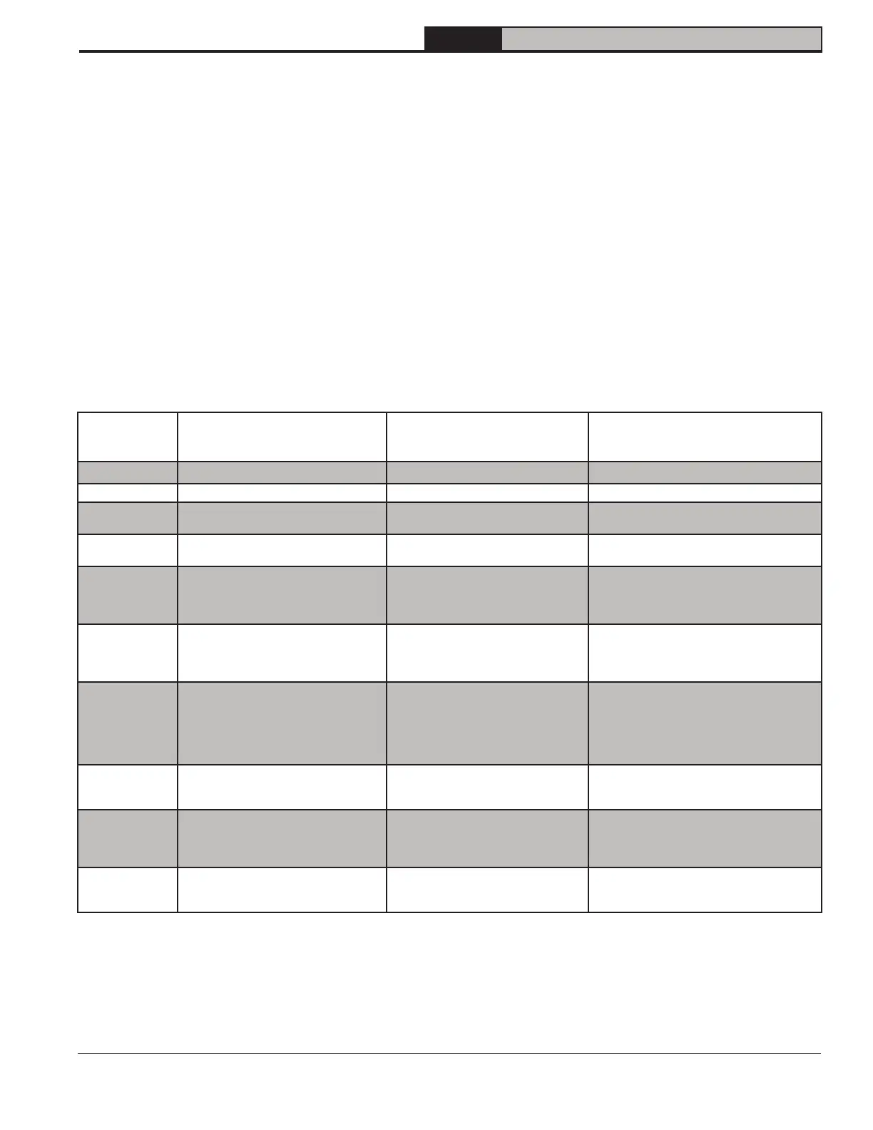
Table 10-4: Green LED Flame Codes
Green LED
Flash
Code
a
Indicates Next System Action Recommended Service Action
OFF No “Call for Heat” N/A None
Flash Fast Power up - internal check N/A None
Heartbeat
Normal startup - ignition sequence
started (including prepurge)
N/A None
4 Seconds ON
then “x” flashes
Device in run mode.
“x” = flame current to the nearest µA.
N/A None
2
5 minute Retry Delay
- Pilot flame not detected during trial for
ignition
Initiate new trial for ignition after retry
delay completed.
If system fails to light on next trial for ignition
check gas supply, pilot burner, spark and
flame sense wiring, flame rod contamination
or out of position, burner ground connection.
3
Recycle
- Flame failed during run
Initiate new trial for ignition. Flash code
will remain through ignition trial until
flame is proved.
If system fails to light on next trial for ignition,
check gas supply, pilot burner, flame sense
wiring, contamination of flame rod, burner
ground connection.
4 Flame sensed out of sequence
If situation self corrects within 10
seconds, control returns to normal
sequence. If flame out of sequence
remains longer than 10 seconds, con-
trol will resume normal operation 1 hour
after error is corrected.
Check for pilot flame. Replace gas valve if pi-
lot flame present. If no pilot flame, cycle “Call
for Heat.” If error repeats, replace control.
6 Control Internal Error
Control remains in wait mode. When
fault corrects, control resumes normal
operation.
Cycle “Call for Heat”. If error repeats, replace
control.
7 Flame rod shorted to ground
Control remains in wait mode. When
fault corrects, control resumes normal
operation.
Check flame sense lead wire for damage or
shorting. Check that flame rod is in proper
position. Check flame rod ceramic for cracks,
damage or tracking.
8
Low secondary voltage supply- (below
15.5 Vac)
Control remains in wait mode. When
fault corrects, control resumes normal
operation.
Check transformer and AC line for proper in-
put voltage to control. Check with full system
load on the transformer.
a
Flash Code Descriptions:
- Flash Fast: rapid blinking
- Heartbeat: Constant ½ second bright, ½ second dim cycles.
- 4 second solid on pulse followed by “x” 1 second flashes indicates flame current to the nearest µA. This is only available in run mode.
- A single flash code number signifies that the LED flashes X times at 2Hz, remains off for two seconds, and then repeats the sequence.
h. Check pilot burner operation/ignition
sequence during ignition cycle:
i. Restore boiler power at circuit
breaker or fuse box.
ii. Set thermostat to call for heat.
iii. Watch ignition sequence at burner.
iv. If spark does not stop after pilot
lights, replace ignition module.
v. If main burners do not light or if main
burners light but system locks out,
check the module ground wire and
gas control as described in Figure
14-1 “ Honeywell Electronic Ignition
Troubleshooting Guide”.
 Loading...