22
FORCE E
Installation, Operating & Service Manual
109444-03 - 12/19
10 Operation
A. Temperature Limit/LWCO Control
Refer to HydroStat 3200 Installation Instructions
and Operating Manual included with these
instructions.
B. Electronic Ignition Module
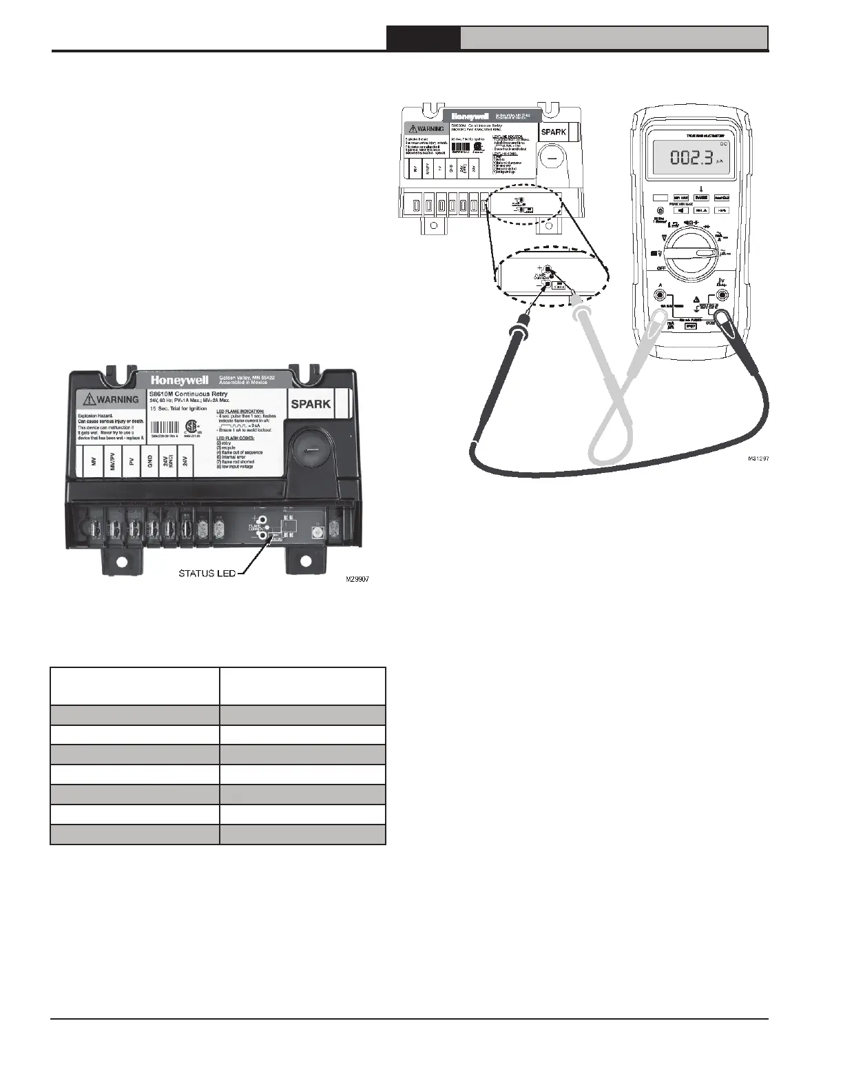
See Figure 10-1 for electronic ignition (EI).
Electronic Ignition Modules with LED indicators.
Table 10-2 cross-references ignition module
terminal designations to ignition terminal numbers
in wiring ladder diagrams. Table 10-4 provides
green LED status codes and recommended
service action where applicable. See Figure
10-1 for Location of LED. See Figure 14-1 for
Troubleshooting Guide.
Figure 10-1: Location of LED
Table 10-2: Ignition Module Terminal Cross-Reference
Ignition Module
Terminal Designation
Wiring Ladder Diagram
Terminal Number
MV 1
MV/PV 2
PV 3
GND 4
24V (GND) 5
24V 6
SPARK SPARK
1. Flame Current Measurement Procedure.
See Figure 10-3 “Measuring pilot flame
current with micro-ammeter”
a. Pilot flame current in micro amps can
be measured using any standard micro-
ammeter by inserting meter probes
into module holes labeled FLAME
CURRENT as shown in Figure 10-3.
Figure 10-3: Measuring Pilot Flame Current
with Micro-ammeter
b. Flame current must be measured with
pilot valve open/pilot lit but main
valve closed.
c. Disconnect MV lead wire from module
before measuring flame current. Trying
to measure pilot flame current in series
with the wiring will not yield accurate
reading.
d. Minimum steady pilot flame signal
must be 1 μAmp (microampere) DC
(direct current).
e. For reliable operation flame current
should be 2 μAmp or greater.
f. To ensure adequate flame current:
i. Turn off boiler power at circuit
breaker or fuse box.
ii. Clean the flame rod with emery cloth
if required.
iii. Make sure electrical connections
are clean and tight, and wiring not
damaged, repair/replace as needed.
iv. Check for igniter/sensor cracked
ceramic insulator, replace if needed.