6
FORCE E
Installation, Operating & Service Manual
109444-03 - 12/19
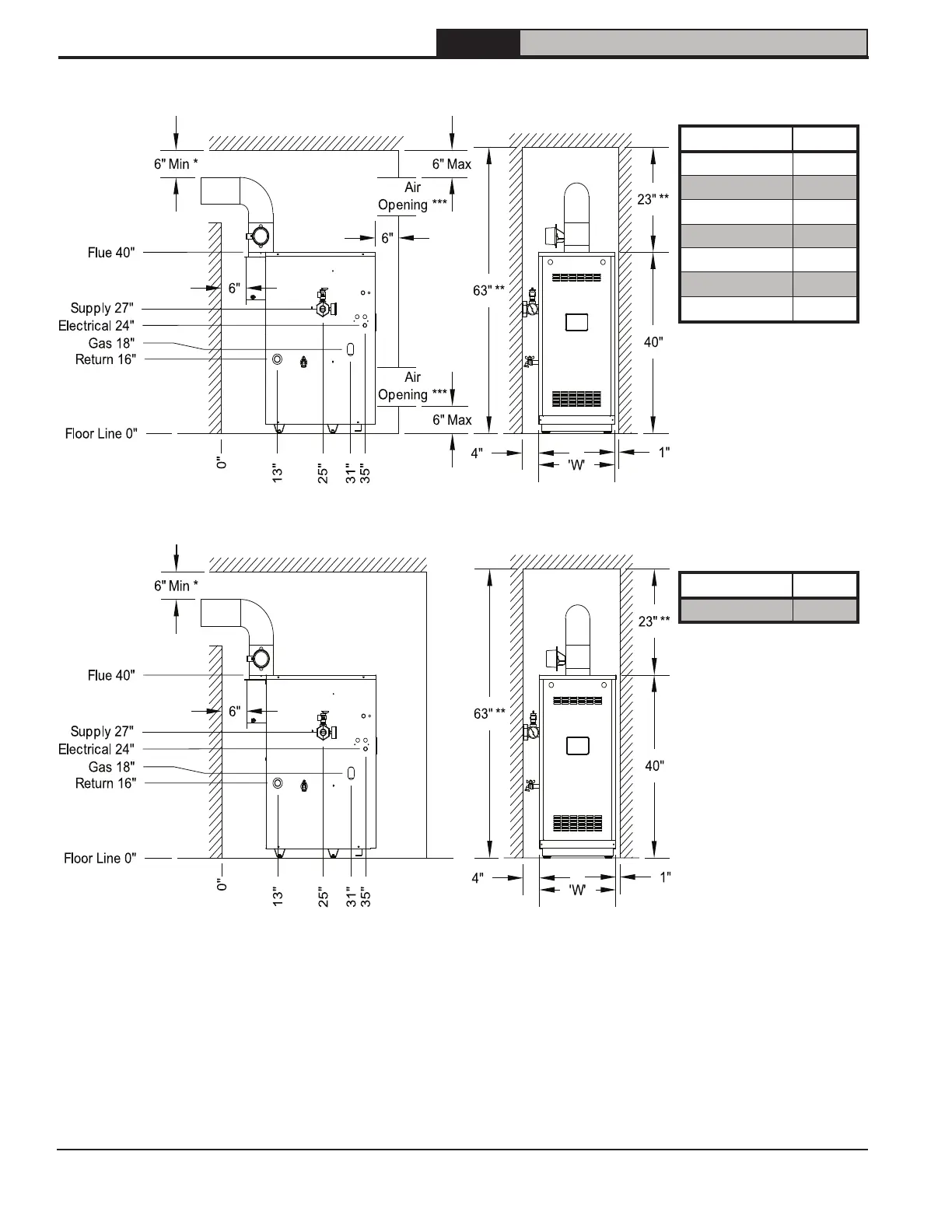
4 Clearances (continued)
Figure 4-1: Minimum Closet Clearances
Model W
FORCE02E 14"
FORCE03E 14"
FORCE04E 16"
FORCE05E 19"
FORCE06E 22"
FORCE07E 25"
FORCE08E 28"
* Minimum radial clearance around vent pipe and breeching for single-wall metal pipe vent connector. Otherwise,
follow vent connector manufacturer's recommended clearances.
** Additional height required to maintain 6" clearance from all vent connector components. Vent damper may be
installed in vertical or horizontal section of vent connector within reach of vent damper harness.
*** Area of each opening to be 1 sq. inch for each 1000 BTU/hr input - with minimum of 100 sq. inches. Height of
opening should be half of width. 3" minimum dimension for air openings.
Model W
FORCE09E 31"
Figure 4-2: Minimum Alcove Clearances