INSTALLATION INSTRUCTIONS
Important note: As an additional safety device, the use of a photocell (safety beam) is recommended
(sold separately).
3. Emergency release
For garages without a second entrance, an emergency release for the mechanical release is necessary
to prevent getting locked in the garage in the event of power failure. The emergency release is door-
specific and must be ordered separately.
Check the function of the emergency release monthly.
Steel Boom Rail Assembly
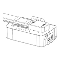
3 Part Boom Rail
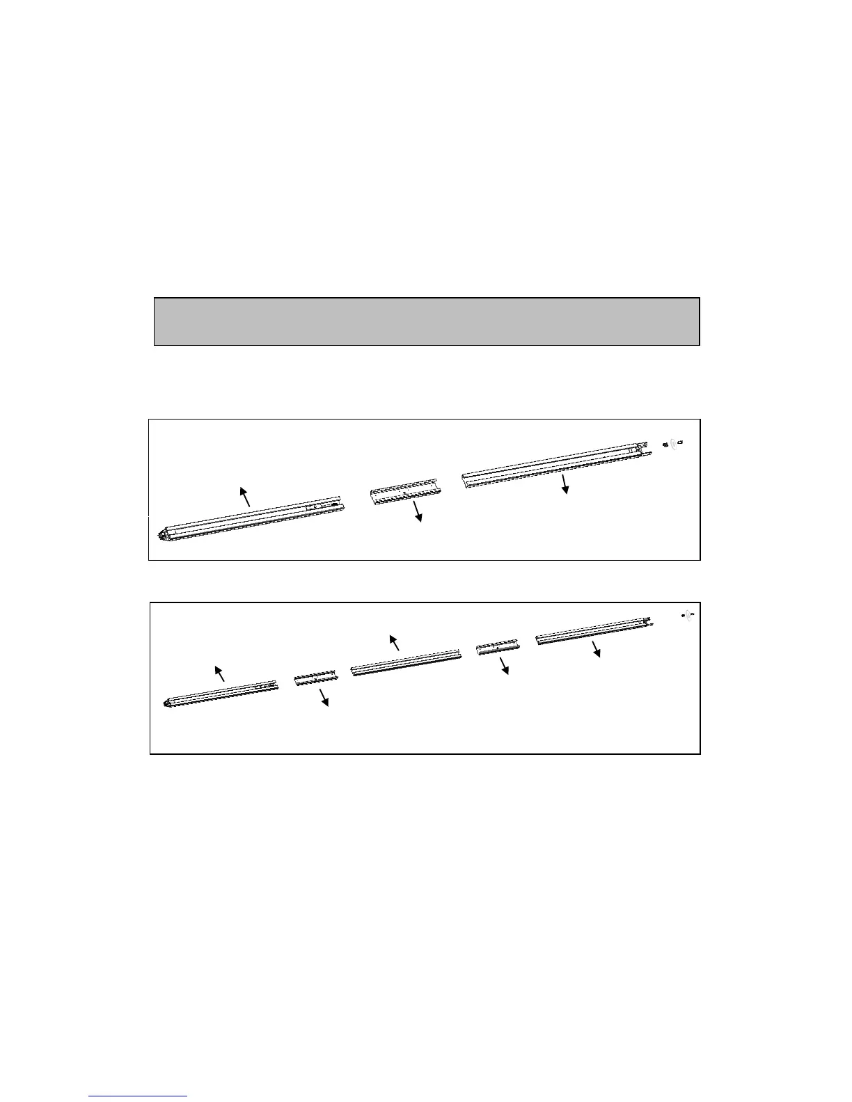
2 Part Boom Rail
A:1500 mm
B:1500 mm
Sleeve
C:1000 mm
Sleeve
Sleeve
D:1000 mm
E:1000 mm
Figure 2
Figure 3
1. 2-Part Rail
As in Figure 2, slide piece A into the sleeve, then slide piece B into the sleeve.
3-Part Rail
As in Figure 3, slide piece C into the first sleeve, followed by piece D. Then slide piece D and E
into the second sleeve
2. Cut the plastic thread; pull the screw rod along with inner belt to the end rail position (Figure 4).
3. Now run the spring and nut on the threaded rod as shown in Figure 5.
4. Tighten the nut to the proper position as shown in Figure 6. Remove the protective film and cut
the last cable ties on the sprocket -- the boom rail assembly is now complete.