1·
22
GROUP 1-
ENGINES
AND
EXHAUST
SYSTEMS
A
VS
B =
VERTICA
L
TAPER
C
VS
D = HOR
IZO
NTAL T
APER
A V$ C AND B
VS
D = OUT-Of-ROUND
CHECK
FOR
OUT-Of-ROUND
AT
EACH
END
OF JOURNAL
I
/
"
I
\
\
\
I I
..
"'
.....
r
~
I
,.
"'"
I I
.,
J J
" I
"-
!..,<W'-_ _ _
~~"
"
.
...
_
-",--"
,
'-"'
:
-'
Al01S-A
FIG.
37-
Crankshafl
Journal
Measuremenl
Check the distributor drive gear
for broken
or
chipped teeth.
REPAIRS
Remove light scuffs, scores,
or
ni
cks from
the
cams
haft
machined
surfaces
with
a smooth oilstone.
CRANKSHAFT
CLEANING
Ha
ndle the c
rank
s
ha
ft with
ca
re
to avoid possible f
ra
ct
ures
or
da
m-
age to the
fi
nished su
rf
aces. Clean the
crankshaft
with solvent, then blow
out all oil passages with compres-
sed air.
INSPECTION
In
spect main and connecting rod
journa
ls
for
cracks,
scratches,
grooves, or score
s.
Measure the diameter
of
each
jour-
nal
in
at
le
ast
four
places to deter-
mine
out
-of-round, taper,
or
under-
size condition (Fig. 37).
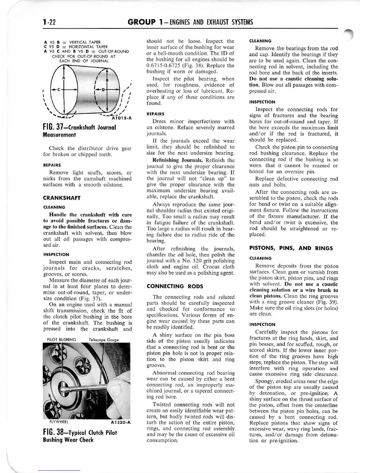
On an engine used with a
manua
l
shift trans
mi
ssion, check
the
fit
of
the clutch pilot bushing in
the
bore
of
the crankshaft.
The
bushing
is
pressed into the
cranks
h
af
t and
FIG
. 38-Typical
Clulch
Pilol
Bushing
Wear
Check
should not be loose. Inspect the
inner surface of the bushing for wear
or a bell-mouth cond
it
io
n.
Th
e
ID
of
the bushing for all engines should be
0.6715-0.6725 (Fi
g.
38). Replace the
bushing
if worn
or
dam
aged.
Inspect the pilot bearing, when
used, for roughness, evidence
of
overheating
or
lo
ss
of
lubricant. Re-
place if any
of
th
ese conditions are
found.
REPAIRS
Dre
ss
minor imperfections with
an oilstone. Reface severely
marred
journals.
Jf
the journals exceed the wear
limit, they sh
ou
ld be refinished to
size for the next undersize bearing.
R
efi
nis
hi
ng
Jo
urnals. Refinish the
journ
al to give the proper clearance
with the next undersize bearing.
If
the j
ourna
l w
ill
not "clean
up"
to
give the proper clearance with the
maximum undersize bearing avail-
able, replace the
cranks
haft.
Always reproduce the same
jour-
nal shoulder radius that existed origi-
nally.
Too
small a radius may result
in fatigue failure of the crankshaft.
Too
lar
ge
a radius
will
result in bear-
ing fai lure due
10 radius ride
of
the
bearing.
Aft
er
refi
ni
shing the journals,
c
hamf
er
the
oi
l hole, then po
li
sh
the
journ
al with a
No
, 320 grit polishing
cloth a
nd
engine oil. Crocus cloth
ma
y also be used as a polishing agent.
CONNECTING RODS
The
connecting rods and related
parts shou
ld
be
caref
ully inspected
and checked for conformance to
specifications. Various forms
of
en-
gine wear caused by
Ihese parts can
be readily
id
entified.
A shiny surface on the pin boss
side
of
the piston usually indicates
that
a connecting rod
is
bent
or
the
pi
ston pin hole is not in
proper
rela-
tion to the
pi
ston skirt and ring
groove
s.
Abnorma
l connect
in
g rod
bear
ing
wear can be
ca
used by eith
er
a bent
connecting rod, an
im
properly
ma
-
chined journal,
or
a tapered connect-
ing rod bore.
Twisted connecting rods will not
create an eas
il
y
id
en
tifi
able wear pat-
tern, but badly twisted rods will dis-
turb
the action
of
the entire piston,
rin
gs,
and connecting rod assembly
and
may be the cause
of
excessive
oi
l
consumption.
CLEANING
Remove
the
be
ar
in
gs from
the
rod
and cap. Identify
the
b
ear
ings if they
are
to
be used again. Clean the con-
necting rod in solvent, including the
rod
bore
and
th
e back
of
the inserts.
Do
n
ot
use a
ca
ustic cleaning solu-
tion.
Blowout
all passages with com-
pressed air.
INSPECTION
In
spect
the
connecting rods for
signs
of
fractures and
the
bearing
bor
es for out-of-round and taper.
It
the
bore
exceeds the maximum limit
and/
or
if the rod
is
fractured, it
should be replaced.
Check the piston pin to connecting
rod
bushing clearance. Replace the
connecting rod if the bushing
is
so
worn that it
cannot
be reamed
or
h
oned
for an oversize pin.
Re
pl
ace defective connecting rod
nut
s and bolts.
After
the
connect
in
g rods are as-
sembled to the
pi
ston, check the rods
for bend
or
twist on a suitable align-
ment fixture. Follow the instructions
of
the fixture manufacturer.
If
the
bend
and/or
twi
st is excessive, the
rod
should be straightened
or
re-
placed.
PISTONS
,
PINS,
AND
RINGS
CLEANING
Remove deposits from the piston
s
urf
aces. Clean gum
or
varnish from
the
pi
ston skirt,
pi
ston pins, and rings
with solvent.
Do
not use a
ca
ustic
clea
ni
ng
so
lution or a wi
re
br
ush to
clean pistons. Clean the ring grooves
with a ring groove cl
eane
r (Fig. 39).
Make sure the oil ring slots (or holes)
are c
le
an.
INSPECTION
Carefu
lly
in
spect
the
pistons for
fractures
at
the ring land
s,
skirt, and
pin bosses,
and
for scuffed,
roug
h,
or
scored skirt
s.
I f the lower inner por-
tion
of
the
ring
grooves have high
step
s,
replace
the
piston.
The
step will
inte
rf
e
re
with ring operation and
cause
excessive ring side clearance.
Spongy, eroded
areas
near
the edge
of
the
piston top
are
us
ua
ll
y caused
by detonation,
or
pre-ignition. A
shiny s
urf
ace
on
the
thrust surface
of
the
piston, offset f
rom
the centerline
between
the
piston p
in
holes,
can
be
ca
used by a
bent
conn
ec
ting rod.
Replace pistons th
at
show signs
of
excessive wear, wavy ring lands, frac-
ture
s,
and
/or
damage
from
detona-
tion
or
pre
-i
gnition.
 Loading...