EasyManua.ls Logo

Ford 1963 Thunderbird - Automatic Transmissions

Ford 1963 Thunderbird
95 pages
Print Icon
To Next Page IconTo Next Page
To Previous Page IconTo Previous Page
Loading...
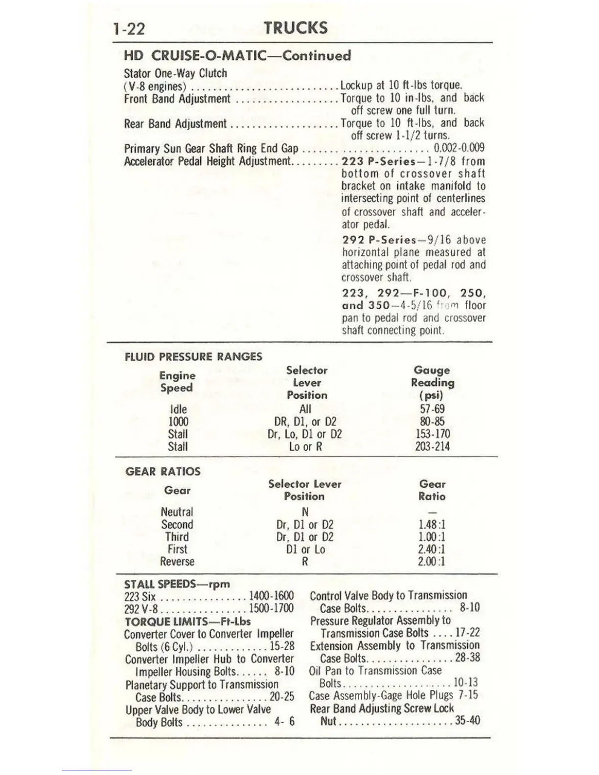
1-22
TRUCKS
HO
CRUISE
-O-
MA
TIC-Continued
Stator
One
·
Way
Clutch
(V
·8
engines
)
..............
.....
..
......
Lockup
at
10
ft
·Ibs
torq
u
e.
Front
Band
Adjustment
.....
•
...
•
...
•.
....
Torque
to
10
in·
lb
s.
and
back
off
screw
one
full
turn
.
Rear
8and
Adjustment
....................
Torque
10
10
ft·lbs.
and
back
off
screw
1·1/ 2
turns
.
Primary
Sun
Gear
Sh
aft
Ring
End
Gap
.................
. . .
...
0.
002
·0
.
009
ActeIerator
Pedal
Height
Adjustment
.........
223 P-Se<ies- l ·7/ 8
from
bottom of crossover shaft
bracket
on
intake
manifold
to
intersecting
point
of
centerlines
of
crossover
s
haft
and
acce
ler·
a
to
r pe
dal.
FLUID
PRESSURE
RANGES
292
P-Series
- 9/16 above
horizontal
plane
measured
at
attaching
point
of
pedal
rod
and
cro
ssove
r
shaft.
223, 292- F-100, 250,
and
350
- 4-5/16 '
l'i
l'l1
fl
oo
r
pan
to
pedal
r
od
and
cross
ove
r
shaft
connect
i
ng
point.
Engine
Speed
Selector
Gouge
Readi
ng
(psi)
57
·
69
80
·
85
153
·
170
203·214
Lever
Position
All
Idle
lin)
Stall
Stall
DR
,
Dl
, or
02
Or,
Lo
,
01
or
02
Lo
or
R
GEAR
RATIOS
Gear
Selector
Lever
Position
Goor
Rat
io
N
Neutral
Second
Third
First
Dr,
Dl
or
D2
Dr
,
Dl
or
02
Dl
or
Lo
1.48
:1
1.00
:1
2.40:
1
2
.00:
1
Reverse
STAll SPEEDS-rpm
223
Six
....
........
....
1400·1600
292V
·8
................
1500·1700
TORQUE
LlMITS
-
Ft-
lbs
Converter
Cover
to
Converte
r
Impeller
Bolts
(6
Cyl.
)
.............
15
·
28
Converter
Impeller
Hub
to
Converter
Impell
er
Housing
80Its
.
...
..
8·10
Planetary
Support
to
Transmission
Case
801ts
.
....
.
.. ..
......
20·25
Upper
Valve
Body
to
Lower
Valve
Body
Bolts
..
. . .. ..
.. ..
...
4· 6
R
Control
Valve
Body
to
Transmission
Case
Bolts..
.. . .
.. ..
. ..
...
8·
10
Pressure
Regulator
Assembly
to
Transmission
Case
Bol
ts
.
...
17
·
22
Exte
n
sion
Assembly
to
Transmission
Case
Bolts
......
..........
28
·38
Oil
Pan
to
Tran
s
mission
Case
Bolls
................
....
10
·
13
C
ase
A
ssembly·Gage
H
ole
Plug
s 7·15
Rear
Band
Adjusting
Screw
Lock
Nut.
................
....
35·40

Table of Contents