STEERING
POWER
STEERING-Continued
POWER
ST
EERING PUMP AND C
ON
T
ROL
VALVE
ADJ
UST
MENTS
AND
TO
LERAN
CE
S
2-31
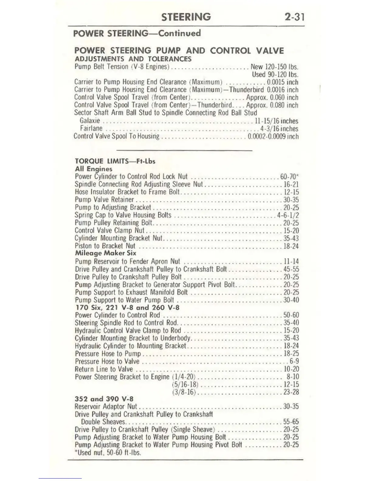
Pump
Belt
Tension
(
Y·8
Engines
)
.......................
New
120
·150
Ibs.
Used
90·120
I
bs.
Carrier
10
Pump
Housing
End
Clearance
(
Maximum
)
............
0.
0015
in
ch
Carrier
to
Pump
Hou
si
ng
End
Clearance
(
Maximum
)-
Thunderbird
0.1J016
inch
Control
Valve
Spool
Travel
(
from
Center
)
................
Appro,.
0.
060
inch
Contro
l
Valve
Spool
Trav
el (
from
Center
)-
Thunderbird
.
...
Appro,
.
O.OBO
inch
Sector
ShaH
Arm
Ball
Stud
to
Spindle
Connecting
Rod
Ball
Stud
Gala,ie
..........
...
....
..........
...........
....
. .
1l
.
15
/
16mches
F
airlane
....
..........
.....
............. .............
4·3/
16
in
ches
Control
Valve
Spool
To
HouslIIg
........
...
....
.....
..
...
0.0002
·
0.0009
inch
TORQUE
Ll
MI
TS
-F
,·
Lb.
All
En
gines
Power
Cylinder
to
Control
R
od
Lock
Nut
..........................
60·70'
Spindle
Connecting
Rod
Adjusling
Sleeve
Nut
......•...
•
............
16
·1
1
Ho
se
Insul
ato
r
Bracket
to
Frame
Boll
..............................
1
2·15
Pump
Valve
Retainer
.................................
..
.....
.
..
30·35
Pump
to
Adjusting
Bracket
......................................
20
·
25
Spring
Cap
to
Valve
Hou
s
ing
Bolt
s
..............................
4
-6
·1/2
Pump
Pulley
Retaining
Bolt.
...........
....
......................
20·25
Control
Valve
Clamp
Nul.
.........................
.
.............
15·20
Cylinder
Mounling
Bracket
Nut.
............
.
.......
..
...
..
.......
35·
43
Pislon
to
Brackel
Nul
..........................................
18
·
24
Mile
ag
e
Mak
er
S
ix
Pump
Reservoir
to
fender
Apron
Nut
...........................
. .
11
·
14
Dr
ive
Pulley
and
Crankshaft
Puliey
to
Crankshaft
Boll
................
45
·55
Drive
Pulley
to
Cranksl"ft
Pulley
Bolt
.............................
20·25
Pump
Adjusling
Bracket
to
Generator
Support
Pivol
Bolt.
......
•
......
20·25
Pump
Support
to
Exhaust
Manifold
Bolt
.....
...
.........
......
....
20
·
25
Pump
Su
pport
to
Waler
Pump
Boll
......
..........
......
...
......
30·
40
170
Si
x, 221 v-a and
26
0 V-8
Power
Cylinder
10
Conlrol
Rod
.................
..
................
50·60
Stee
r
ing
Spindle
Rod
to
Control
Rod
............
....
.....
..
........
35·
40
Hydraulic
Control
Valve
Clamp
to
Rod
.............................
15
·
20
Cy
l
inder
Mounting
Brackel
to
Underbody
.........•.............
.
...
35
·
43
Hydraulic
Cy
l
inde
r
to
Mounti
ng
Bracket.
..........
.
................
1
8·24
Pressure
Hose
10
Pump
.........................................
1
8·25
Pressure
Hose
10
Va
l
ve
...........................................
6·9
Return
Line
to
Yalve
.........
.
............................
. . .. .
10
·20
Power
Sleering
Brackello
Engine
(l
/4·
20
) ..
.....
•
...
...
.....
. . ..
..
8·10
(
5/16·18
)
.......
.
.......
.
........
12
·15
352
a nd 3
90
V·S
(3/
8·16
) .
........................
23
·
28
Reservoir
Adaptor
Nut
........
.
..
........
.....
.
.................
30·35
Dr
ive
Pu
ll
ey
and
Crankshaft
Pu
ll
ey
to
Crankshaft
Double
Sheaves
.....
.
......
....
. .
.................
. .
..
.....
. .
55·65
Drive
Pu
liey
to
Crankshafl
Pu
lley
(
Single
Sheave
)
.............•.....
20
·
25
P
ump
Adjus
l
ing
Brackello
Waler
Pu
mp
Housing
Bo
lt
...
.
............
20
·
25
Pump
Adjusting
Bracket
to
Wa
l
er
Pump
Housing
Pivol
Bolt
...
..
•
.....
20
·
25
'
Used
nul.
50
·
60
fI
·lbs.



 To Next Page