----------------CHAPTER 1----------------
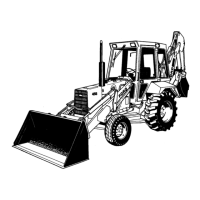
Figure 8
Exhaust Valve Assembly
1. Spring Retainer 3. Exhaust Valve
Locks 4. Spring Retainer
2. Seal 5. Spring
Figure 9
Rocker Shaft Disassembled
1. Spring 4. Rocker Arm
2. Retaining Bolt 5. Shaft
3. Shaft Support 6. Spacer
VALVE SEATS:
5. Examine the valve seat inserts and reface if pitted
but replace if damaged. If necessary, install an
oversize insert by machining the seat counterbore
in the cylinder head, see "Specifications," Chapter
3. The insert must be chilled in dry-ice prior to
installation.
PRINTED
IN U.S.A.
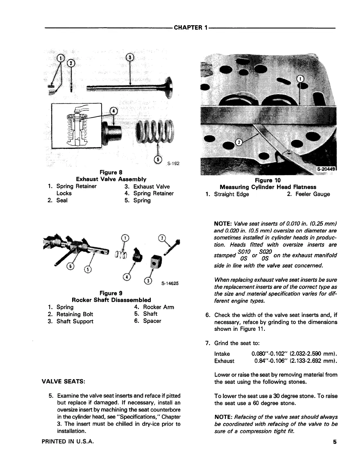
Figure 10
Measuring Cylinder Head Flatness
1. Straight Edge 2. Feeler Gauge
NOTE: Valve seat inserts of 0.010 in. (0.25 mm)
and 0.020 in. (0.5 mm) oversize on diameter are
sometimes installed in cylinder heads in produc-
tion. Heads fitted with oversize inserts are
SOTO S020 .
stamped OS or OS on the exhaust manifold
side in line with the valve seat concerned.
When replacing exhaust valve seat inserts be sure
the replacement inserts are of the correct type as
the size and material specification varies for dif-
ferent engine types.
6. Check the width of the valve seat inserts and, if
necessary, reface by grinding to the dimensions
shown in Figure 11.
7. Grind the seat to:
Intake
Exhaust
0.080"-0.102" (2.032-2.590 mm).
0.84"-0.106" (2.133-2.692 mm).
Lower or raise the seat by removing material from
the seat using the following stones.
To lower the seat use a 30 degree stone. To raise
the seat use a 60 degree stone.
NOTE: Refacing of the valve seat should always
be coordinated with refacing of the valve to be
sure of a compression tight fit.
5
 Loading...