-------------PART
1 -
ENGINE SYSTEMS-------------
n
S-20344
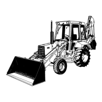
Figure
11
Valve Seat
Dimensions
1. Valve Seat Angle: 2. Valve Seat Width:
45° 00' -45° 30' for Intake 0.080-0.102
all Valve Seats in. (2.032-2.590
mml
Exhaust 0.084-
0.106 in. {2.133-
2.692 mm)
VALVES:
6
8. Examine the valve face and, if pitted, replace or
reface by grinding to the dimension shown in
Figure
12.
Before refacing the valve, be sure the
valve stem is not bent or worn and check the valve
seat run-out, measured at right-angles to the seat,
does not exceed a total of 0.0015 in. (0.038 mm).
Measure the valve head margin to assure sufficient
margin remaining after refacing.
S-20345
Figure 12
Intake and Exhaust Valves
1. Valve-Margin 0.031 2. Valve-Face Angle
in. (.787 mm)
minimum
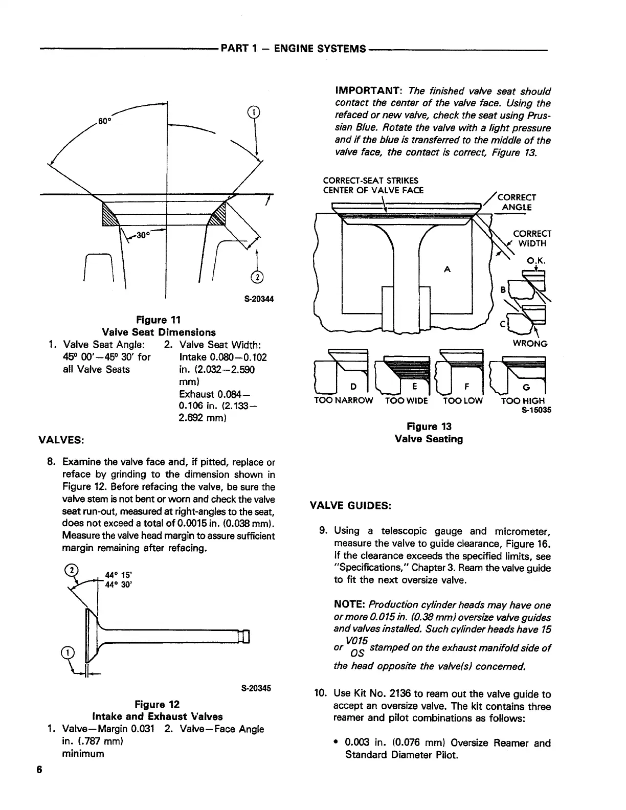
IMPORTANT:
The finished valve seat should
contact the center of the valve face. Using the
refaced or new valve, check the seat using Prus-
sian Blue. Rotate the valve with a light pressure
and if the blue is transferred to the middle of the
valve face, the contact is correct, Figure 13.
CORRECT-SEAT STRIKES
CENTER OF VAL VE FACE
l.
/CORRECT
~=======·1==============::;:
ANGLE
CORRECT
WIDTH
O.K.
A
t
·~
cc9
WRONG
m~ITT~
TOO
NARROW
TOO WIDE TOO LOW
VALVE GUIDES:
Figure 13
Valve Seating
TOO HIGH
S-15035
9. Using a telescopic gauge and micrometer,
measure the valve to guide clearance, Figure
16.
If the clearance exceeds the specified limits, see
"Specifications," Chapter 3. Ream the valve guide
to fit the next oversize valve.
NOTE:
Production cylinder heads may have one
or more 0.015 in. (0.38 mm} oversize valve guides
and valves installed. Such cylinder heads have 15
or
vg~
stamped on the exhaust manifold side of
the head opposite the valve(s) concerned.
10.
Use Kit No.
2136
to ream out the valve guide to
accept an oversize valve. The kit contains three
reamer and pilot combinations as follows:
• 0.003 in. (0.076 mm) Oversize Reamer and
Standard Diameter Pilot.
 Loading...