----------------CHAPTER 1----------------
• 0.015 in. (0.38 mm) Oversize Reamer and 0.003
in. (0.076 mm) Oversize Pilot.
• 0.030 in. (0.76 mm) Oversize Reamer and 0.015
in. {0.38 mm) Oversize Pilot.
When going from a standard valve stem to an
oversize always use the reamers in sequence.
After reaming a valve guide, always check the
valve seating and reface if necessary.
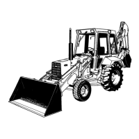
Figure 14
Measuring Valve Guide
1. Telescopic Gauge 2. Micrometer
VALVE SPRINGS:
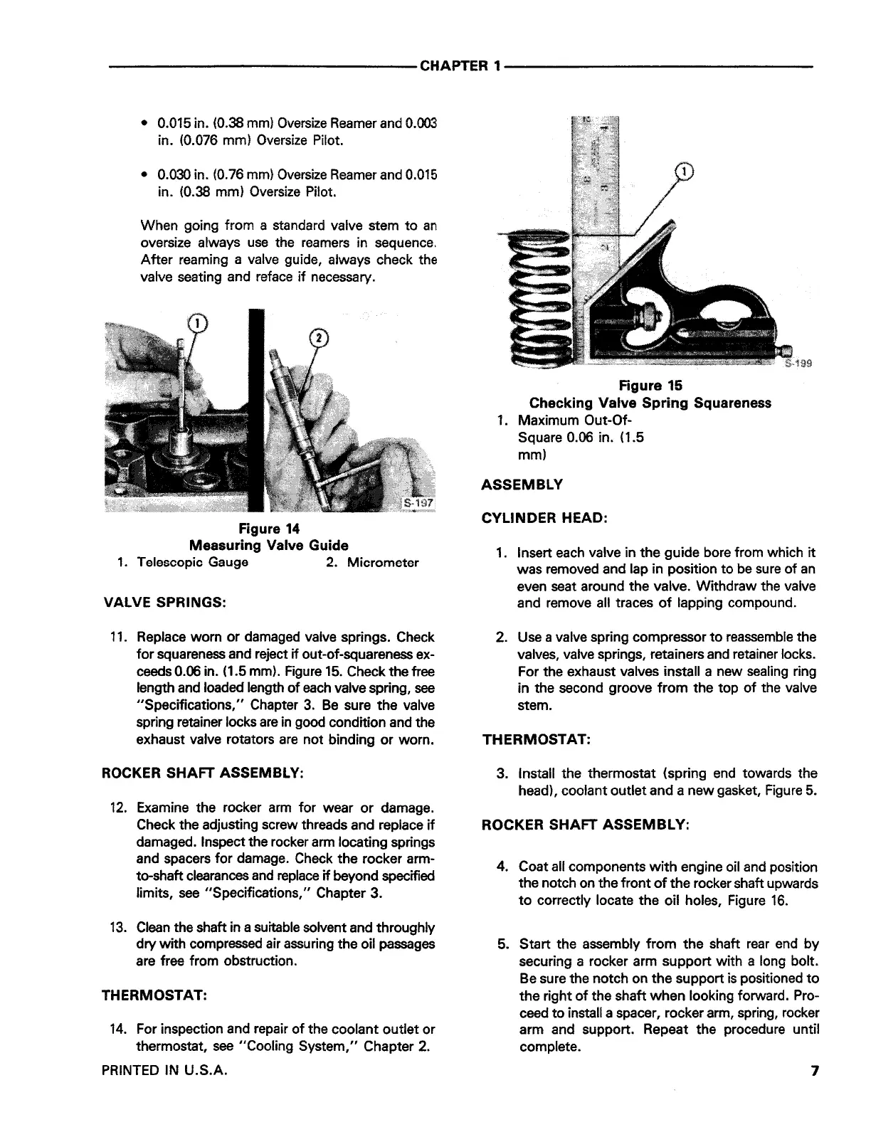
11. Replace worn or damaged valve springs. Check
for squareness and reject if out-of-squareness ex-
ceeds 0.06 in. (1.5 mm). Figure 15. Check the free
length and loaded length of each valve spring,
see
"Specifications," Chapter 3. Be sure the valve
spring retainer locks are in good condition and the
exhaust valve rotators are not binding or worn.
ROCKER SHAFT ASSEMBLY:
12. Examine the rocker arm for wear or damage.
Check the adjusting screw threads and replace if
damaged. Inspect the rocker arm locating springs
and spacers for damage. Check the rocker arm-
to-shaft clearances and replace if beyond specified
limits, see "Specifications," Chapter 3.
13. Clean the shaft in a suitable solvent and throughly
dry with compressed air assuring the oil passages
are free from obstruction.
THERMOSTAT:
14. For inspection and repair of the coolant outlet or
thermostat, see "Cooling System," Chapter 2.
PRINTED
IN U.S.A.
Figure 15
Checking Valve Spring Squareness
1 . Maximum Out-Of-
Square 0.06 in. (1.5
mm)
ASSEMBLY
CYLINDER HEAD:
1. Insert each valve in the guide bore from which it
was removed and lap in position to be sure of an
even seat around the valve. Withdraw the valve
and remove all traces of lapping compound.
2. Use a valve spring compressor to reassemble the
valves, valve springs, retainers and retainer locks.
For the exhaust valves install a new sealing ring
in the second groove from the top of the valve
stem.
THERMOSTAT:
3. Install the thermostat (spring end towards the
head), coolant outlet and a new gasket, Figure 5.
ROCKER SHAFT ASSEMBLY:
4. Coat all components with engine oil and position
the notch on the front of the rocker shaft upwards
to correctly locate the oil holes, Figure 16.
5. Start the assembly from the shaft rear end by
securing a rocker arm support with a long bolt.
Be sure the notch on the support is positioned to
the right of the shaft when looking forward. Pro-
ceed to install a spacer, rocker arm, spring, rocker
arm and support. Repeat the procedure until
complete.
7
 Loading...