------------PART 1 - ENGINE SYSTEMS------------
~ONT
Of
ENGINE
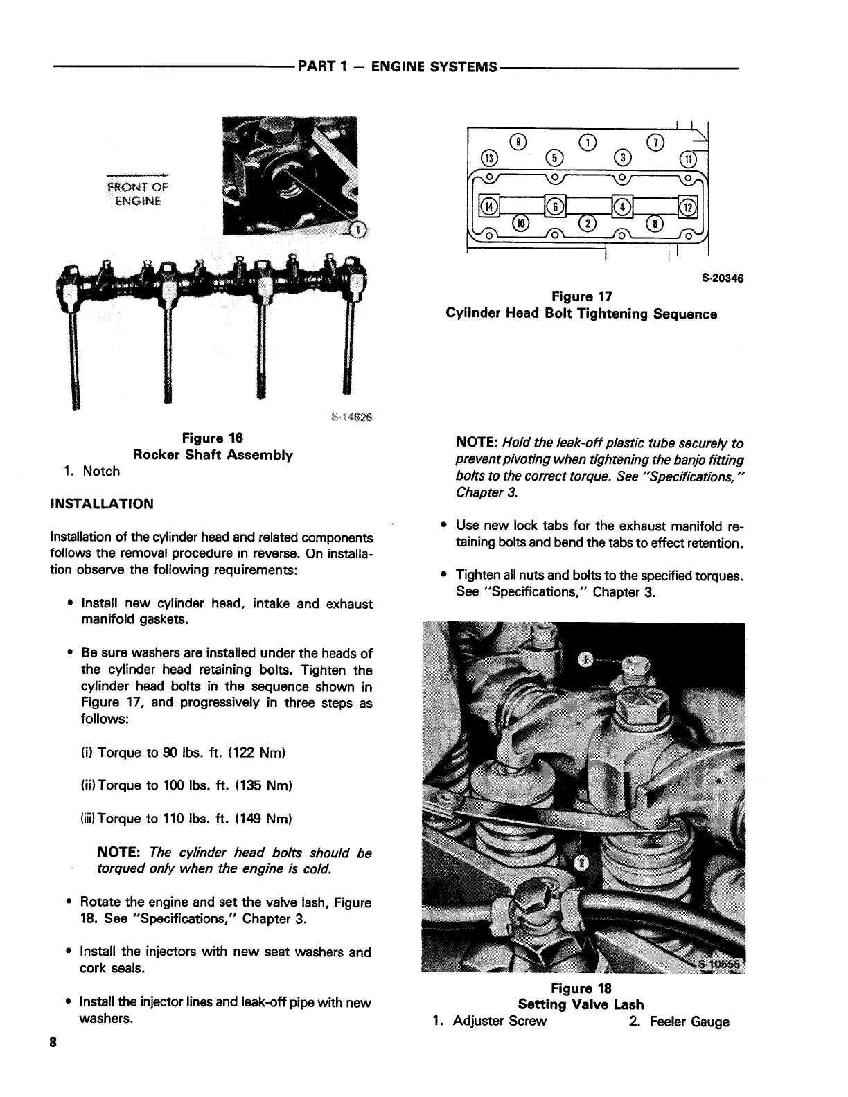
Figure 16
Rocker Shaft Assembly
1. Notch
INSTALLATION
Installation of the cylinder head and related components
follows the removal procedure in reverse. On installa-
tion observe the following requirements:
8
• Install new cylinder head, intake and exhaust
manifold gaskets.
• Be sure washers are installed under the heads of
the cylinder head retaining bolts. Tighten the
cylinder head bolts in the sequence shown in
Figure 17, and progressively in three steps as
follows:
(i)
Torque to 90 lbs.
ft.
(122 Nm)
(ii)Torque to 100 lbs.
ft.
(135 Nm)
(iii)Torque to 110 lbs.
ft.
(149 Nm)
NOTE:
The cylinder head bolts should be
torqued only when the engine is cold.
• Rotate the engine and set the valve lash, Figure
18. See "Specifications," Chapter 3.
• Install the injectors with new seat washers and
cork seals.
• Install the injector lines and leak-off pipe with new
washers.
CD
0
0
S-20346
Figure 17
Cylinder Head Bolt Tightening Sequence
NOTE:
Hold the leak-off plastic tube securely to
prevent pivoting when tightening the banjo fitting
bolts to the correct torque. See "Specifications, "
Chapter 3.
• Use new lock tabs for the exhaust manifold re-
taining bolts and bend the tabs to effect retention.
• Tighten all nuts and bolts to the specified torques.
See "Specifications," Chapter 3.
Figure 18
Setting Valve Lash
1. Adjuster Screw 2. Feeler Gauge
 Loading...