-------------PART 1 - ENGINE SYSTEMS-------------
2. Examine the gear teeth for wear, burrs or
scratches. Any minor burrs or scratches may be
removed with a fine abrasive; be sure aH parts are
throughly washed before reassembly.
3. Be sure the camshaft drive gear adapter oil
passage is free from obstruction and the drive gear
bushing is not damaged.
4. Check the key and keyway in the end of both the
camshaft and crankshaft for damage. Replace the
keys if necessary.
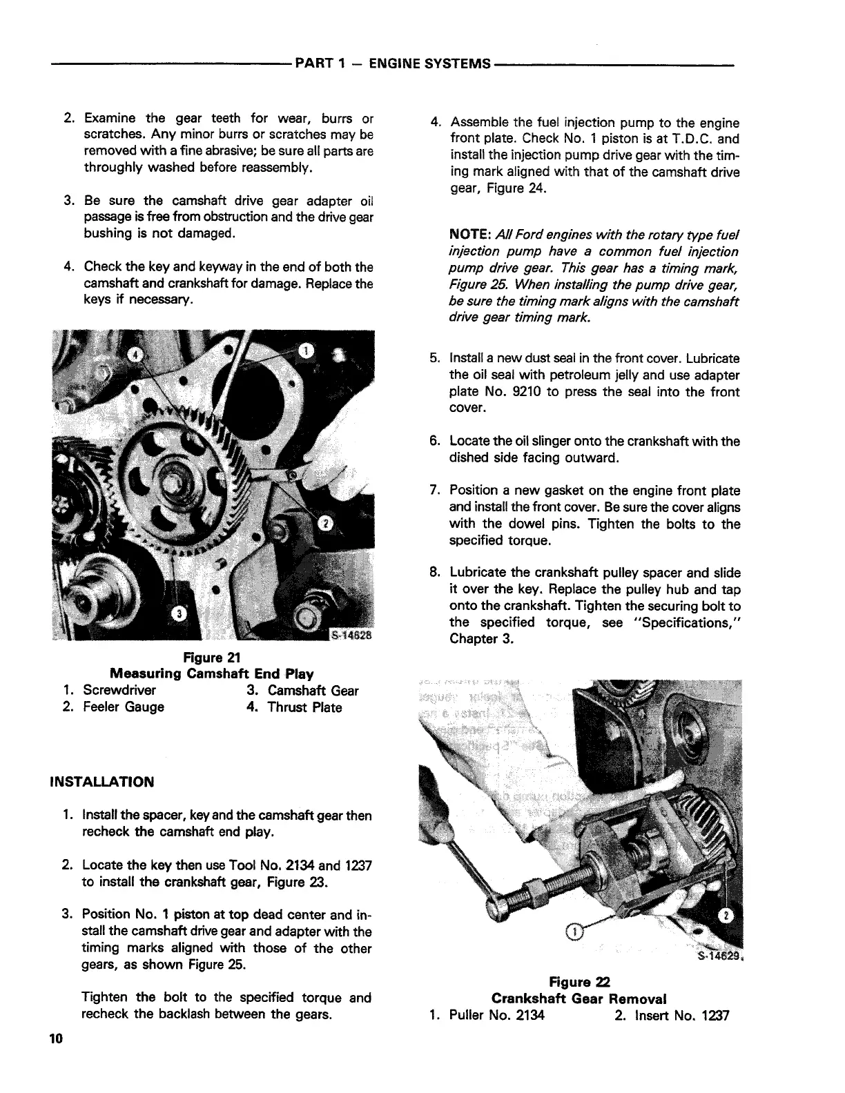
Figure 21
Measuring Camshaft End Play
1. Screwdriver 3. Camshaft Gear
2. Feeler Gauge 4. Thrust Plate
INSTALLATION
1. Install the spacer, key and the camshaft gear then
recheck the camshaft end play.
2. Locate the key then use Tool No. 2134 and 1237
to install the crankshaft gear, Figure 23.
3. Position No. 1 piston at top dead center and in-
stall the camshaft drive gear and adapter with the
timing marks aligned with those of the other
gears, as shown Figure 25.
10
Tighten the bolt to the specified torque and
recheck the backlash between the gears.
4. Assemble the fuel injection pump to the engine
front plate. Check No. 1 piston is at T.D.C. and
install the injection pump drive gear with the tim-
ing mark aligned with that of the camshaft drive
gear, Figure 24.
NOTE:
All Ford engines with the rotary type fuel
injection pump have a common fuel injection
pump drive gear. This gear has a timing mark,
Figure 25. When installing the pump drive gear,
be sure the timing mark aligns with the camshaft
drive gear timing mark.
5. Install a new dust seal in the front cover. Lubricate
the oil seal with petroleum jelly and use adapter
plate No. 9210 to press the seal into the front
cover.
6. Locate the oil slinger onto the crankshaft with the
dished side facing outward.
7. Position a new gasket on the engine front plate
and install the front cover. Be sure the cover aligns
with the dowel pins. Tighten the bolts to the
specified torque.
8. Lubricate the crankshaft pulley spacer and slide
it over the key. Replace the pulley hub and tap
onto the crankshaft. Tighten the securing bolt to
the specified torque, see "Specifications,"
Chapter 3.
Figure 22
Crankshaft Gear Removal
1. Puller No. 2134 2. Insert No. 1237
 Loading...