----------------CHAPTER
1----------------
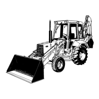
Figure 48
Typical Bearing Failures
1. Overlay Worn 3. Scratches
2. Radii Ride
4. lmbedded Dirt
4. If a new thrust bearing liner is installed, the bear-
ing must be aligned as described in the CRANK-
SHAFT section of this Chapter.
5. Install the oil pump and intermediate shaft, and
the oil pan.
FLYWHEEL:
REMOVAL
1. Separate the tractor between the engine and the
transmission, see "Separating the Tractor," Part
12.
2. Remove the pressure plate and clutch disc
assembly from the flywheel, see "Clutches," Part
4.
5. Craters or Pockets
6. Fatigue Failure
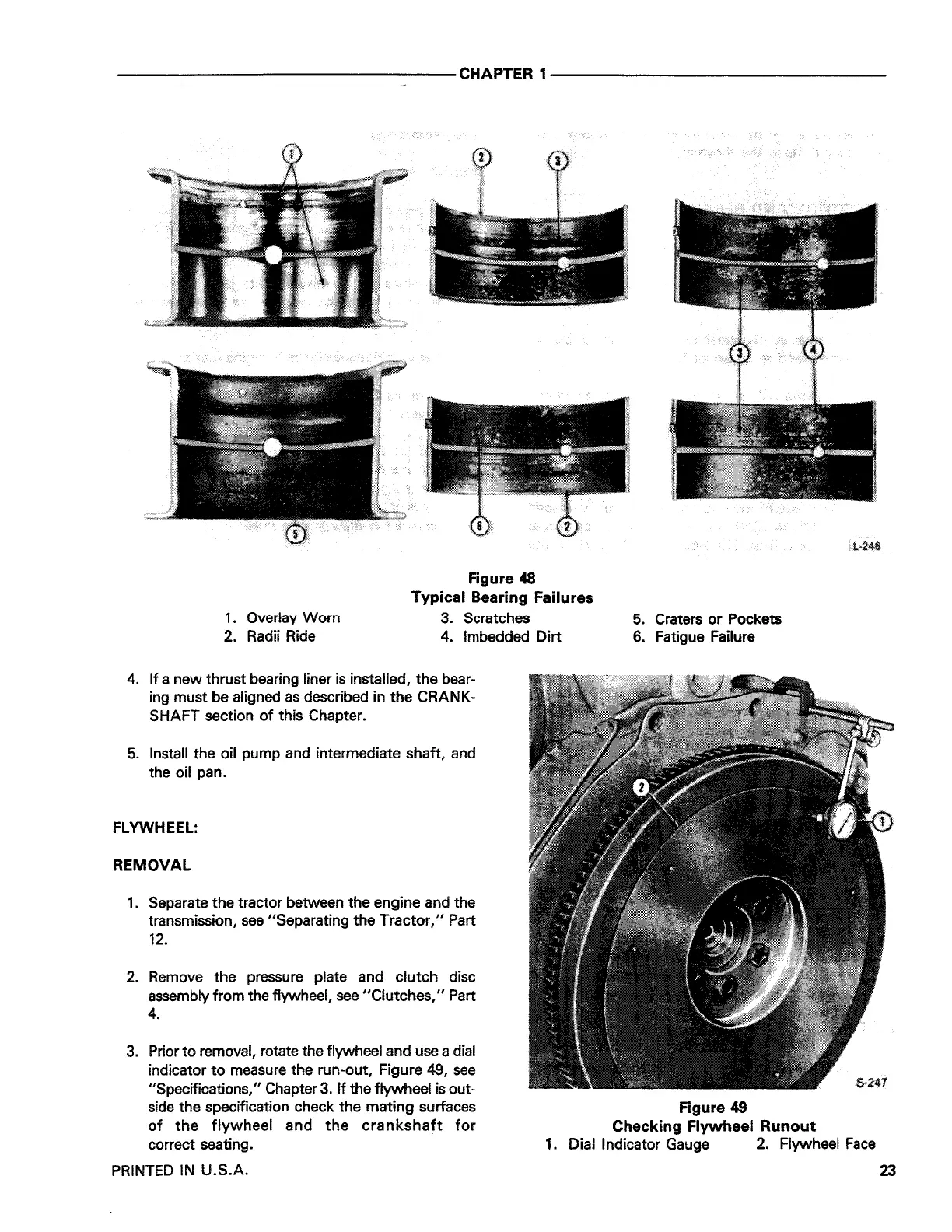
Figure 49
Checking Flywheel Runout
3. Prior to removal, rotate the flywheel and use a dial
indicator to measure the run-out, Figure 49, see
"Specifications," Chapter 3. If the flywheel is out-
side the specification check the mating surfaces
of the flywheel and the crankshaft for
correct seating.
1. Dial Indicator Gauge 2. Flywheel Face
PRINTED IN U.S.A.
23
 Loading...