------------PART 1 - ENGINE SYSTEMS-------------
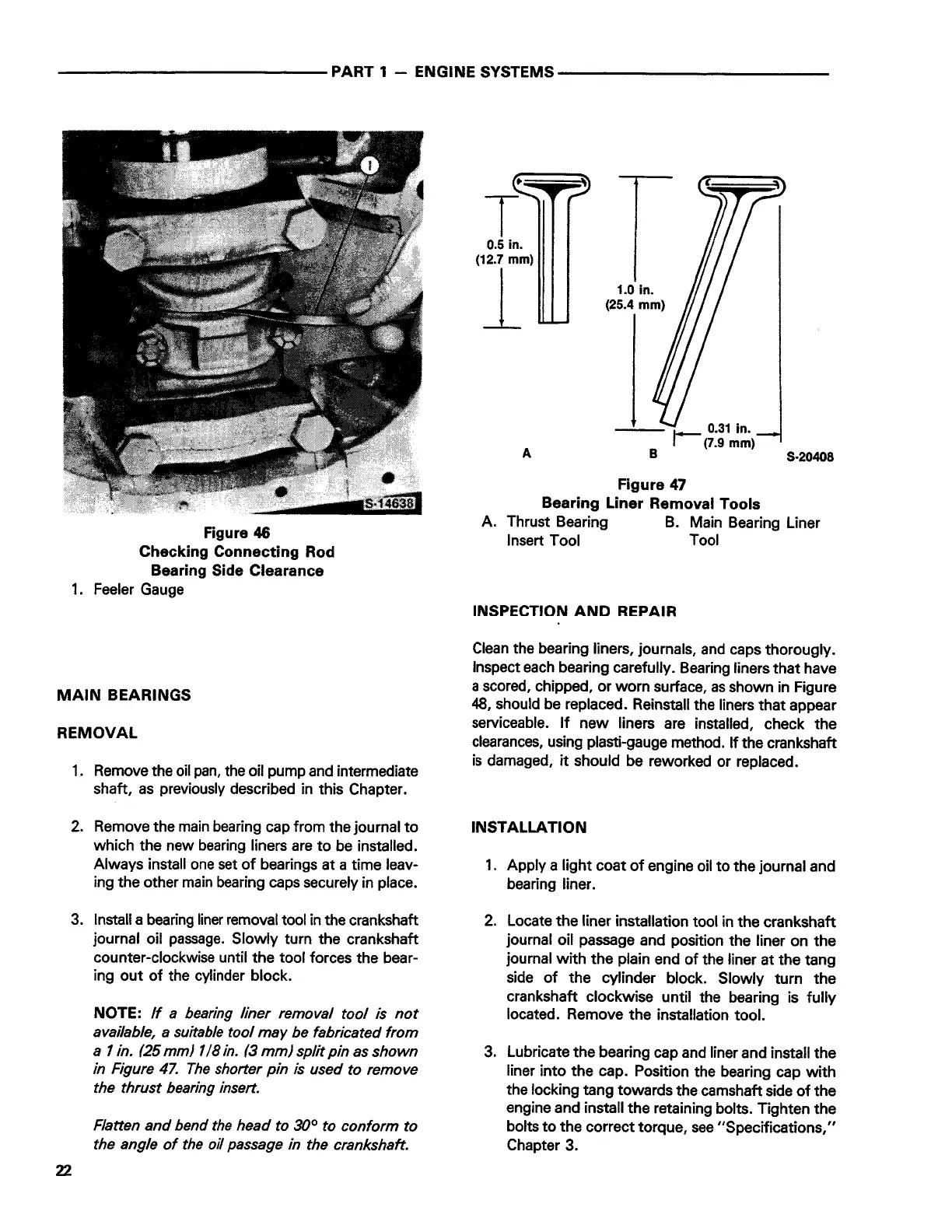
Figure 46
Checking Connecting Rod
Bearing Side Clearance
1. Feeler Gauge
MAIN BEARINGS
REMOVAL
1. Remove the oil pan, the oil pump and intermediate
shaft, as previously described in this Chapter.
2. Remove the main bearing cap from the journal to
which the new bearing liners are to be installed.
Always install one set of bearings at a time leav-
ing the other main bearing caps securely in place.
3. Install a bearing liner removal tool in the crankshaft
journal oil passage. Slowly turn the crankshaft
counter-clockwise until the tool forces the bear-
ing out of the cylinder block.
22
NOTE:
If a bearing liner removal tool is not
available, a suitable tool may be fabricated from
a 1 in. (25 mm) 1 /8 in. (3 mm) split pin as shown
in Figure 47. The shorter pin is used to remove
the thrust bearing insert.
Flatten and bend the head to 30° to conform to
the angle of the oil passage in the crankshaft.
0.5
in.
(12.7
mm)
1
A
1.0
in.
(25.4
mm)
Figure 47
Bearing Liner Removal Tools
S-20408
A. Thrust Bearing B. Main Bearing Liner
Insert Tool Tool
INSPECTION AND REPAIR
Clean the bearing liners, journals, and caps thorougly.
Inspect each bearing carefully. Bearing liners that have
a scored, chipped, or worn surface, as shown in Figure
48, should be replaced. Reinstall the liners that appear
serviceable. If new liners are installed, check the
clearances, using plasti-gauge method. If the crankshaft
is damaged, it should be reworked or replaced.
INSTALLATION
1. Apply a light coat of engine oil to the journal and
bearing liner.
2. Locate the liner installation tool in the crankshaft
journal oil passage and position the liner on the
journal with the plain end of the liner at the tang
side of the cylinder block. Slowly turn the
crankshaft clockwise until the bearing is fully
located. Remove the installation tool.
3. Lubricate the bearing cap and liner and install the
liner into the cap. Position the bearing cap with
the locking tang towards the camshaft side of the
engine and install the retaining bolts. Tighten the
bolts to the correct torque, see "Specifications,"
Chapter 3.
 Loading...