----------------CHAPTER 1----------------
2nd Compression Ring:
The 2nd compression ring is dull gray or black and must
be installed in the second groove. When installed, the
side marked "top" must be facing towards the top of
the piston. The step on the inside of the ring will be
facing upwards.
Top Compression Ring
The top compression ring is chrome and must be in-
stalled in the top groove. The top compression ring may
be installed with either side up.
3. After installing the rings, stagger the ring gaps
around the circumferenece of the piston.
INSTALLATION
NOTE:
Before installing a piston and new rings
into a used cylinder bore, remove the high polish
on the cylinder wall by passing a hone lightly
through the cylinder. After honing, thoroughly
wash and dry the bores and coat the walls with oil.
1. Select the correct bearing liners, as described in
the CRANKSHAFT section of this Chapter, and
install in the connecting rod and cap. Be sure the
bearing liner tang located in the slots of the rod
and cap.
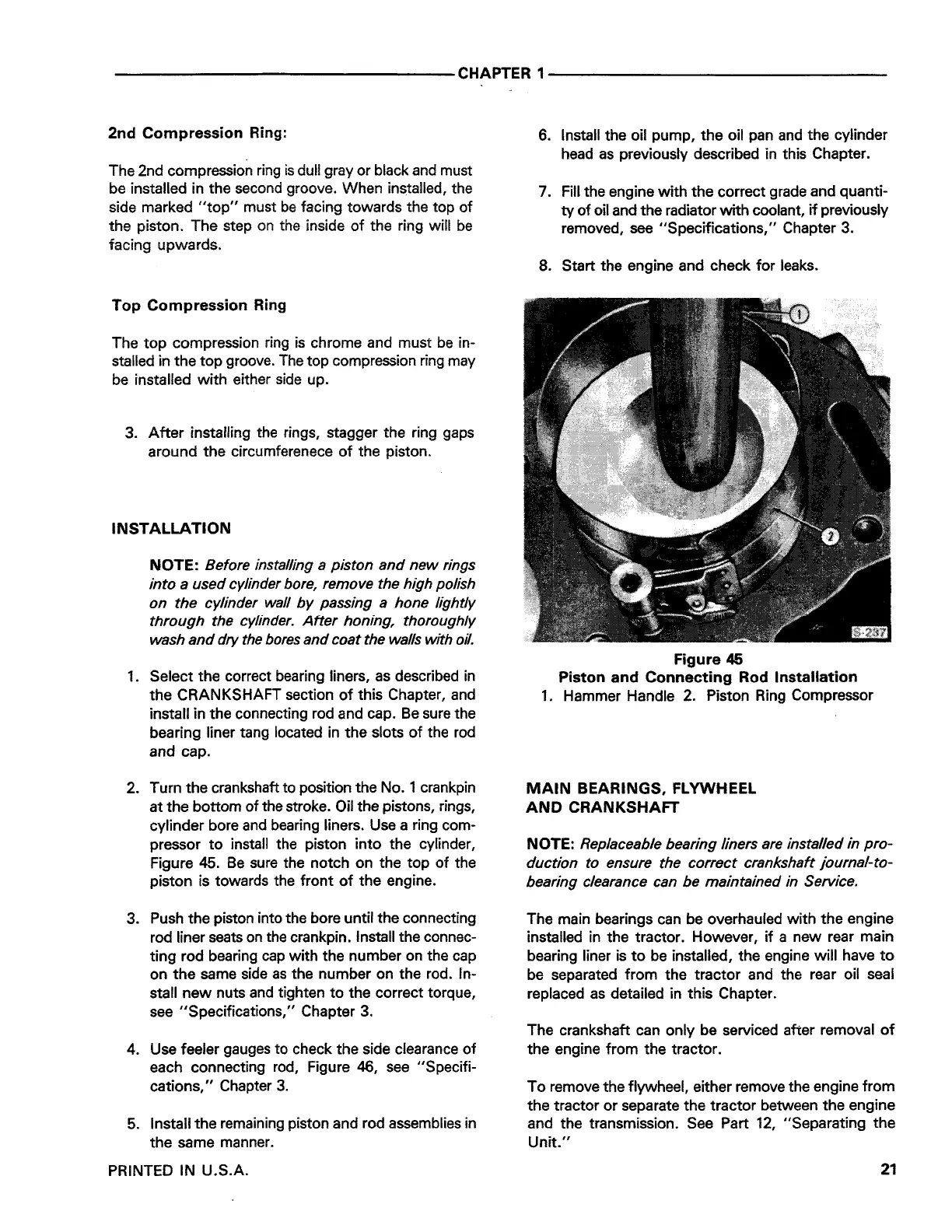
2. Turn the crankshaft to position the No. 1 crankpin
at the bottom of the stroke. Oil the pistons, rings,
cylinder bore and bearing liners. Use a ring com-
pressor to install the piston into the cylinder,
Figure 45. Be sure the notch on the top of the
piston is towards the front of the engine.
3. Push the piston into the bore until the connecting
rod liner seats on the crankpin. Install the connec-
ting rod bearing cap with the number on the cap
on the same side as the number on the rod. In-
stall new nuts and tighten to the correct torque,
see "Specifications," Chapter 3.
4. Use feeler gauges to check the side clearance of
each connecting rod, Figure 46, see "Specifi-
cations," Chapter 3.
5. Install the remaining piston and rod assemblies in
the same manner.
PRINTED IN U.S.A.
6. Install the oil pump, the oil pan and the cylinder
head as previously described in this Chapter.
7. Fill the engine with the correct grade and quanti-
ty of oil and the radiator with coolant, if previously
removed, see "Specifications," Chapter 3.
8. Start the engine and check for leaks.
Figure 45
Piston and Connecting Rod Installation
1. Hammer Handle 2. Piston Ring Compressor
MAIN BEARINGS, FLYWHEEL
AND CRANKSHAFT
NOTE:
Replaceable bearing liners are installed in pro-
duction to ensure the correct crankshaft journal-to-
bearing clearance can be maintained in Service.
The main bearings can be overhauled with the engine
installed in the tractor. However, if a new rear main
bearing liner is to be installed, the engine will have to
be separated from the tractor and the rear oil seal
replaced as detailed in this Chapter.
The crankshaft can only be serviced after removal of
the engine from the tractor.
To remove the flywheel, either remove the engine from
the tractor or separate the tractor between the engine
and the transmission. See Part 12, "Separating the
Unit."
21
 Loading...