-------------PART 1 - ENGINE SYSTEMS-------------
3. Check the piston rings for minimum gap prior to
installation in the relevant cylinder, Figure 43. Use
a piston crown to squarely locate the ring in the
bore. New rings should be checked for side
clearance in the piston as previously described in
this Chapter.
4. Using an expander to install the piston rings, star-
ting with the oil control ring in the bottom groove
and working upwards.
Figure 43
Checking Piston Ring Gap
1. Piston Ring 2. Feeler Gauge
PISTON RINGS:
The piston ring set comprises of:
20
• 2 Compression Rings.
• 1 Oil Control Ring.
• 1 Spiral or rail type Ring Expander for Oil Control
Ring.
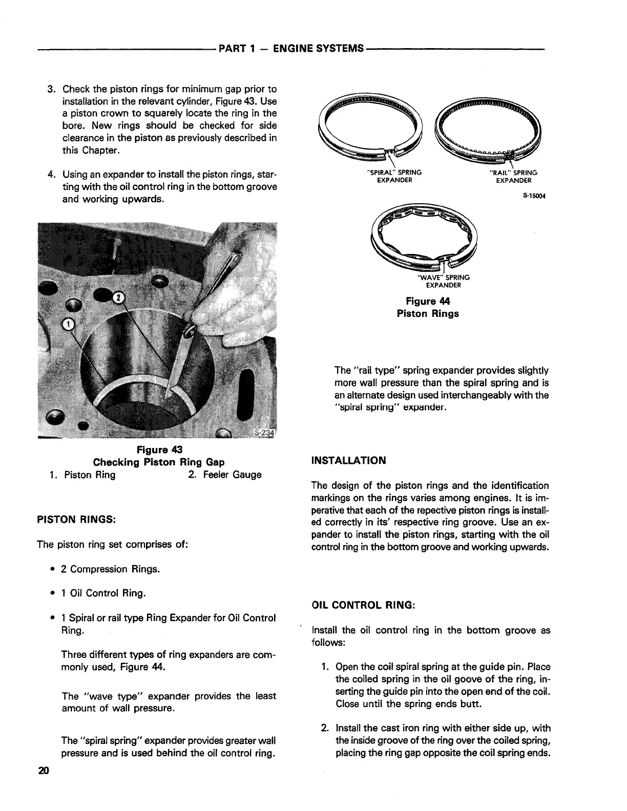
Three different types of ring expanders are com-
monly used, Figure 44.
The "wave type" expander provides the least
amount of wall pressure.
The "spiral spring" expander provides greater wall
pressure and is used behind the oil control ring.
"SPIRAL" SPRING
EXPANDER
'WAVE" SPRING
EXPANDER
Figure 44
Piston Rings
"RAIL" SPRING
EXPANDER
S-15004
The "rail type" spring expander provides slightly
more wall pressure than the spiral spring and is
an alternate design used interchangeably with the
"spiral spring" expander.
INSTALLATION
The design of the piston rings and the identification
markings on the rings varies among engines. It is im-
perative that each of the repective piston rings is install-
ed correctly in its' respective ring groove. Use an ex-
pander to install the piston rings, starting with the oil
control ring in the bottom groove and working upwards.
OIL CONTROL RING:
Install the oil control ring in the bottom groove as
follows:
1. Open the coil spiral spring at the guide pin. Place
the coiled spring in the oil goove of the ring, in-
serting the guide pin into the open end of the coil.
Close until the spring ends butt.
2. Install the cast iron ring with either side up, with
the inside groove of the ring over the coiled spring,
placing the ring gap opposite the coil spring ends.
 Loading...