----------------CHAPTER 1----------------
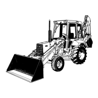
Figure 41
Measuring Piston To Block Height
(iv) Bore and hone the sleeve to the diameter
required. Only standard and 0.004 in. (0.10
mm) oversize pistons can be used with the
thin walled 4.4 in. (111.76 mm) bore sleeve.
13. Check the flatness of the cylinder block-to-head
surface, see "Specifications," Chapter 3.
ASSEMBLY
NOTE:
Prior to assembly, check the cylinder bores
for taper and out-of-round previously described
in this Chapter.
1. Prior to assembly, check the piston-to-bore
clearance as follows:
• Measure the cylinder bore diameter in a
crosswise direction then measure the piston
diameter at right angles to the piston pin.
• Subtract the piston diameter from the bore
diameter and the resultant figures should be
within specified clearance, see "Specifica-
tions," Chapter 3.
NOTE:
Pistons are available in both standard
and oversizes. New pistons should be install-
ed ff the clearance exceeds the specffied limits.
PRINTED IN U.S.A.
• If the clearance is
greater
than specified, try
a similar new piston. If the clearance still ex-
ceeds the specified limit, measure the other
cylinder bores with the greatest clearance. Bas-
ed on the greatest clearance, rebore the
cylinders to take the next oversize piston as
previously described in this Chapter.
• If the clearance is
less
than specified: Hone the
bore to obtain the desired clearance previous-
ly described in this Chapter.
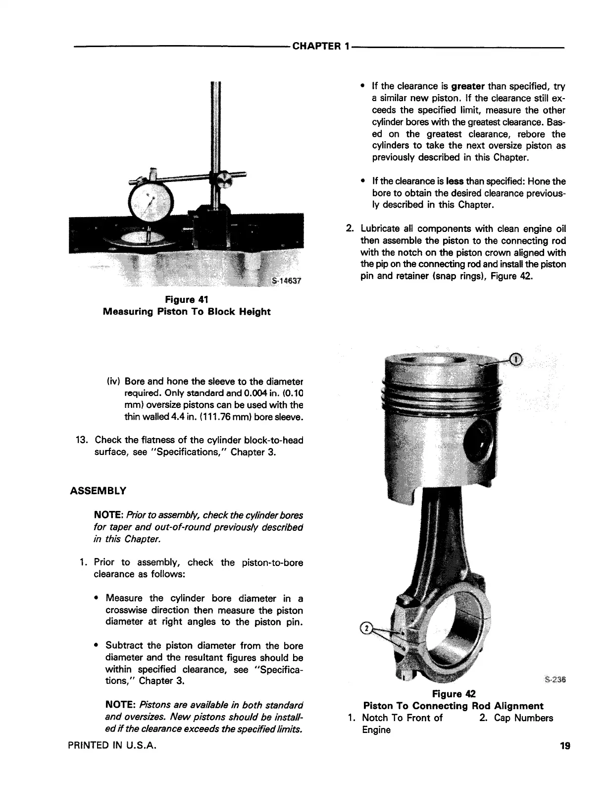
2. Lubricate all components with clean engine oil
then assemble the piston to the connecting rod
with the notch on the piston crown aligned with
the pip on the connecting rod and install the piston
pin and retainer {snap rings), Figure 42.
Figure 42
Piston To Connecting Rod Alignment
1. Notch To Front of 2. Cap Numbers
Engine
19
 Loading...